Speckle blood flow imaging method and device based on component analysis

A component analysis and imaging method technology, applied in the field of biological tissue optical blood flow imaging, can solve the problems of being easily affected by image jitter, low image temporal resolution, low image spatial resolution, etc. The effect of high resolution and high imaging accuracy

Active Publication Date: 2017-12-19
佳维斯(武汉)生物医药有限公司
View PDF13 Cites 10 Cited by
  • Summary
  • Abstract
  • Description
  • Claims
  • Application Information

AI Technical Summary

Problems solved by technology

[0004] Spatial contrast imaging method: For example, Chinese invention patent CN1391869A "Method for detecting spatiotemporal response characteristics of microcirculation blood flow on intestinal thin membrane by using laser speckle imager", the main disadvantage of this method is that the spatial resolution of the image is low
Time-contrast imaging method: For example, the Chinese invention patent CN1792323A "a high-resolution imaging method and device for transcranial blood flow". The main disadvantage of this method is that the time resolution of the image is low and it is easily affected by image shake
Time-space combined contrast imaging method: Chinese invention patent CN101485565A "a laser speckle blood flow imaging analysis method" and Chinese invention patent CN102429650A "a laser speckle blood flow imaging contrast analysis method", both methods use The method of combining spatial contrast imaging and temporal contrast imaging improves the spatial resolution and temporal resolution of imaging, but there are problems of excessive calculation and slow speed of the algorithm

Method used


Image

  • Speckle blood flow imaging method and device based on component analysis
  • Speckle blood flow imaging method and device based on component analysis
  • Speckle blood flow imaging method and device based on component analysis

Examples


Embodiment Construction

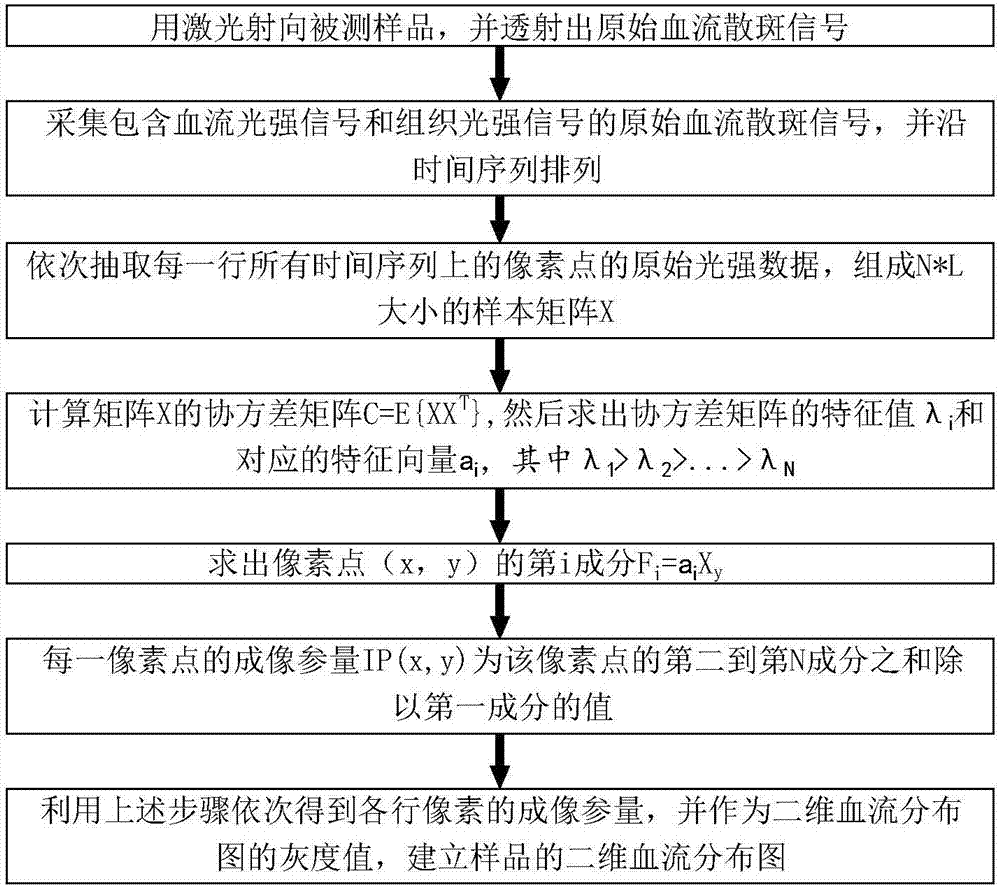
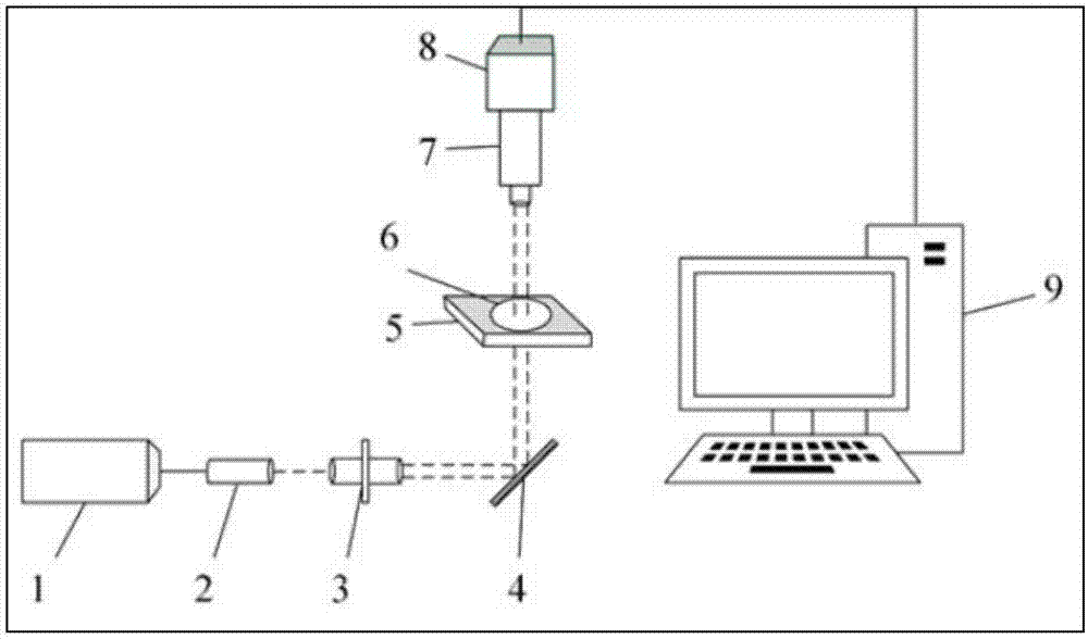
[0040] refer to figure 1 , a speckle blood flow imaging method based on component analysis of the present invention, comprising the following steps:

[0041] The laser is irradiated to the sample to be tested, and the original blood flow speckle signal is transmitted;

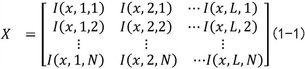
[0042] Collect the original blood flow speckle signals including blood flow light intensity signals and tissue light intensity signals, and arrange them in time series;

[0043] The components of the original blood flow speckle signal are analyzed to obtain the blood flow light intensity signal produced by the moving red blood cells and the tissue light intensity signal produced by the background tissue;

[0044]Calculate the imaging parameters of each pixel of the blood flow profile;

[0045] Using the above steps, the imaging parameters of each row of pixels are sequentially obtained, and used as the gray value of the two-dimensional blood flow distribution map to establish a two-dimensional blood flow dist...


PUM


Abstract

The invention discloses a speckle blood flow imaging method and device based on component analysis. The method comprises the steps of performing component analysis on an original blood flow speckle signal, separating out a blood flow light intensity signal and a tissue light intensity signal, calculating out an imaging parameter, utilizing the imaging parameter as a gray value of a two-dimensional blood flow distribution diagram and establishing a two-dimensional blood flow distribution diagram of a sample. The method has the advantages of no invasion, no contrast medium injection, no damage and the like; the method can be applied to living small animal samples like blood flow imaging of mice, fish embryo and the like; the method has great application prospect in pathology diagnosis and analysis of a part of blood flow diseases. The device has the advantages of low cost, no damage to samples, ability in quickly achieving blood flow imaging, high imaging accuracy and application to blood flow monitoring; a transmission type imaging system is utilized, so that a deeper imaging depth is obtained; a long-focus telecentric lens is introduced into, so that blood flow at a deep position is in a focus depth range, a camera can collect clear images, and a higher spatial resolution is obtained.

Description

technical field [0001] The invention relates to the field of optical blood flow imaging of biological tissues, in particular to a speckle blood flow imaging method and device based on component analysis. Background technique [0002] Laser speckle blood flow imaging belongs to the field of optical imaging technology. It obtains blood flow information by collecting speckle signals of biological tissues. It can obtain the blood flow distribution map of the whole field without injection of contrast agent and mechanical scanning. It has non-destructive and non-contact imaging advantages. At present, laser speckle blood flow imaging technology has been successfully applied to blood flow imaging and monitoring of cerebral cortex, skin, eye retina and other tissues, which is of great significance for the pathological diagnosis and analysis of some blood flow diseases. [0003] The speckle blood flow imaging method usually continuously collects N frames of speckle images with a siz...

Claims


Application Information

Patent Timeline
Patent Type & Authority Applications(China)
IPC IPC(8): A61B5/026G06T11/00
CPCA61B5/0261A61B5/72G06T11/00
Inventor 王茗祎关财忠毛文健曾亚光谭海曙韩定安熊红莲
Owner 佳维斯(武汉)生物医药有限公司
Why Eureka
Try Eureka