Combined type production line of heat retaining non-dismantling formwork for building and production method

A technology that avoids dismantling formwork and production lines, and is applied to the preparation of building components on site, construction, building construction, etc., and can solve problems such as production interruption, limited output, and inequalities

Inactive Publication Date: 2018-01-05
绿建科技集团新型建材高技术有限公司
View PDF12 Cites 5 Cited by
  • Summary
  • Abstract
  • Description
  • Claims
  • Application Information

AI Technical Summary

Problems solved by technology

[0019] The defect of this technical scheme is, 1, this technical scheme is a single production line, and output is limited, if want to enlarge output, according to this technical scheme, just need to build production line more, must install raw material warehouse more, install mixer more, install hopper more, The cost of equipment is relatively high, which wastes resources. 2. In this technical solution, one end of the screw conveyor is connected to the first pulp distribution machine, and the other end is connected to the other pulp distribution machine. One screw conveyor, and multiple raw material bins are required to match multiple screw conveyors
3. In this patent document, uniform material distribution cannot be achieved. In this technical solution, an insulation material spreading device is provided between the insulation mixture feeding device and the upper mesh cloth laying device, and the insulation material spreading device includes a vibrating motor , a spring and a guide plate, the lower part of the guide plate is arc-shaped towards the heat preservation mixture feeding device, and the guide plate is connected to the vibration motor through a spring
The defect of this device is: in actual operation, piles of thermal insulation slurry are continuously placed on the mold, and as the conveyor belt moves forward, the thermal insulation slurry will be more and more blocked in front of the arc-shaped vibrating guide plate, and the working After a long time, a large amount of thermal insulation slurry will accumulate in front of the arc vibrating guide plate. As the thermal insulation slurry accumulates more and more, to a certain extent, the arc vibrating guide plate will be buried, and the conveyor belt will also be damaged. Stuck, so that the conveyor belt can not continue to run forward, the production was forced to stop
[0021] The product of this technical solution is to make surface reinforcement layers on both sides of the polystyrene board. This product is quite different from the product of this patent technology. This product can also be used as a cast-in-place external formwork for buildings, but it is not suitable for external walls. The interior insulation and the cast-in-place exterior formwork of the floor slab cannot be decorated indoors, because the nails are embedded in the polystyrene board and it is difficult to fix the decoration objects, causing the decoration objects to fall
And the polystyrene board is easy to age and burn
Secondly, this technical solution is a technical solution for a single production line. If you want to expand the output, according to this technical solution, you need to build multiple same production lines repeatedly, and you must build multiple raw material warehouses and multiple feeding systems.
Again, this technical solution needs to place a large number of molds on the conveyor belt to produce, and requires a large number of equipment such as mold assembly racks, splitting systems, loading systems, and mobile hangers.
Fourth, this technical solution is aimed at using ordinary cement as a surface reinforcement layer on both sides of the polystyrene board, so the solidification, molding, and curing time are long, and a large number of molds need to be placed on the conveyor belt to produce, requiring a lot of maintenance equipment and maintenance. site
[0023] The defect of the product of this technical scheme has: the polyurethane foam sandwiched between the double hard surfaces has low strength and is easy to age, and cannot be used as a cast-in-place external formwork for buildings; secondly, it is difficult to fix decoration objects when nails are embedded in the polyurethane foam. It causes the decoration objects to fall, so it is not suitable for the cast-in-place external formwork for external wall internal insulation and floor slabs. The production method and production line of this product are not the same as this patented technology
[0025] The defects of the products of this technical solution are as follows: 1. This patent can only produce and process insulation boards with single-layer coverage, and cannot adapt to the processing requirements of the current upper and lower coverage surfaces and the middle insulation layer
2. The polystyrene board is very soft. The composite thermal insulation board produced according to this technical plan cannot meet the strength requirements of the building's cast-in-place external formwork, and is not suitable for external wall insulation and floor slab cast-in-place external formwork. It cannot be used indoors. For decoration, because the nails are embedded in the polystyrene board, it is difficult to fix the decoration object, causing the decoration object to fall
3. Polystyrene board is easy to age and burn
6. This technical solution is aimed at using ordinary cement as the single-layer covering surface of polystyrene board, so it takes a long time for solidification, molding, and maintenance. It needs to place a large number of molds on the conveyor belt to produce, and requires a large number of maintenance equipment and maintenance sites.
[0030] 3. Solve the problems that the product maintenance time is too long, the investment in maintenance equipment is large, and a large amount of maintenance space is occupied

Method used


Image

  • Combined type production line of heat retaining non-dismantling formwork for building and production method
  • Combined type production line of heat retaining non-dismantling formwork for building and production method
  • Combined type production line of heat retaining non-dismantling formwork for building and production method

Examples


Embodiment Construction

[0079] The scope of the present invention is not limited thereto, and the protection scope thereof is described in each claim.

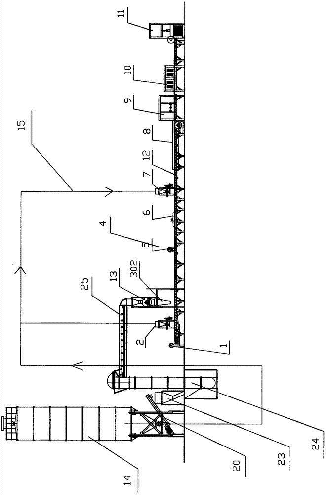
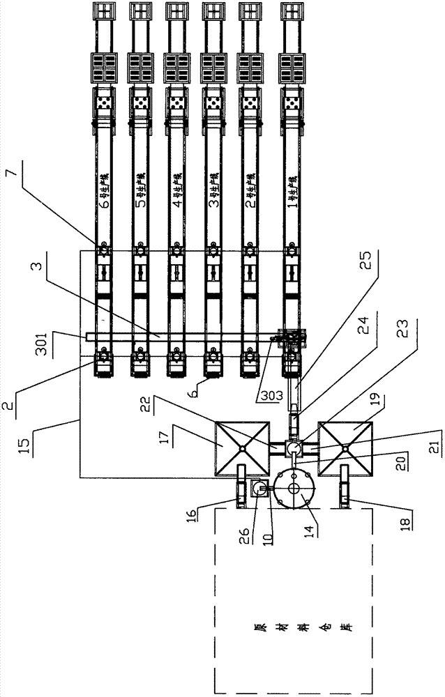
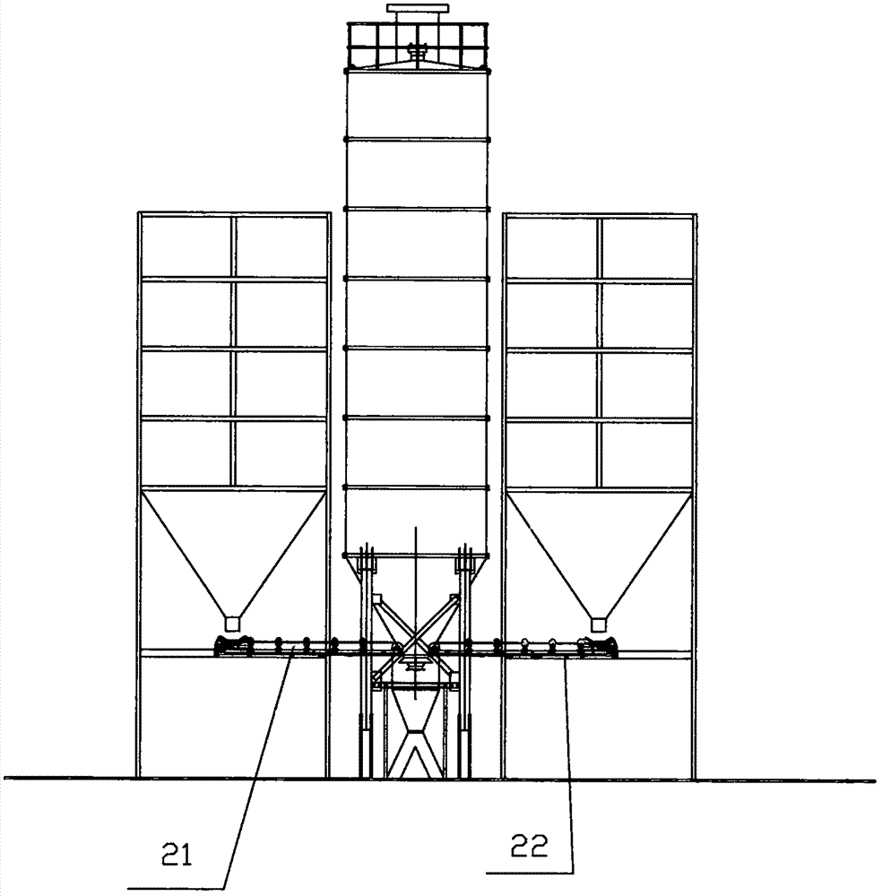
[0080] like figure 1 , figure 2As shown in the figure, a production line for thermal insulation free formwork for buildings is characterized in that the combined production line for thermal insulation free formwork for buildings includes a raw material warehouse, a batching system, a pneumatic conveying device, a mixer, a mobile blanking system, and a combined production line ,Control System,

[0081] The mixer 13 is located above the moving hopper system and supplies materials to the moving feeding system 3;

[0082] Described mobile blanking system 3 comprises frame 301, track, mobile blanking hopper 302, motor 303, and frame 303 spans above the combined production line, track is arranged on frame 301, and running wheel is installed on the mobile blanking hopper 302, The rotating wheel is located on the track, the motor 303 is combined with the...


PUM


Abstract

The invention discloses a combined type production line of a heat retaining non-dismantling formwork for a building. The combined type production line is characterized in that a stirring system is located above a movable feeding system and used for supplying materials to the movable feeding system; the movable feeding system comprises a machine frame, a rail, a movable feeding hopper and a transmission device, the machine frame spans above the combined production line, the movable feeding hopper sequentially supplies the materials to single production lines which are combined together, and thecombined production line is a combination of the production lines which are designed according to capacity requirements. Each single production line comprises a conveying belt mold forming system, abottom layer net paving device, a bottom layer pulp distributing device, a face layer net paving device, a vibration forming device and a face layer pulp distributing device. A gel material conveyingsystem communicates with a raw material bin and the bottom layer pulp distributing device and the face layer pulp distributing device of the single production line. The combined type production line solves the problem that the equipment investment is too large, and solves the problems that the fireproof performance of products is poor, the strength is insufficient, the maintenance time of the products is too long, the maintenance equipment investment is large, and the occupied maintenance filed is large.

Description

technical field [0001] The invention relates to the technical field of construction machinery, in particular to a combined production line and production method of thermal insulation and non-dismantling formwork for construction. Background technique [0002] The insulation-free formwork for buildings includes an insulation layer and a surface reinforcement layer, the insulation layer is located between the surface reinforcement layers, and the insulation layer and the surface reinforcement layer are fixed together. Among them, the surface reinforcement layer is the layer composed of cementitious material and net gelled together, and the insulation layer is composed of one of the three substances of plant dry matter, animal fur, and light aggregate, adding cementitious material or additives. layer; or a layer composed of two of the three substances of plant dry matter, animal fur, and lightweight aggregate and then adding cementitious materials or additives; or a layer compo...

Claims


Application Information

Patent Timeline
Patent Type & Authority Applications(China)
IPC IPC(8): B28B15/00B28B13/02B28B1/093B28B1/52B28B23/00B28B19/00B28C7/04B28C7/06B28C7/10E04G9/10
Inventor 谢向荣
Owner 绿建科技集团新型建材高技术有限公司
Why Eureka
Try Eureka