Ship waste heat step utilization type cold-and-hot electric desalination four-cogeneration device and working method

A cold-heat-electricity, cascade technology, applied in the field of energy engineering, can solve the problems of insufficient waste heat, low waste heat recovery efficiency, equipment corrosion and damage, etc., and achieve the effects of improving heat power conversion capacity, avoiding large noise and high utilization efficiency.

Active Publication Date: 2018-01-05
JIANGSU UNIV OF SCI & TECH
View PDF5 Cites 26 Cited by
  • Summary
  • Abstract
  • Description
  • Claims
  • Application Information

AI Technical Summary

Problems solved by technology

At present, the ship air conditioning system is mainly based on the vapor compression type, supplemented by the absorption type, but the absorption heat pump has more advantages in the utilization of waste heat; because the flue gas contains a large amount of corrosive substances, the flue gas cannot be directly used to drive the absorption heat pump device. Moreover, after the flue gas exhausted by the main engine is used by the two-stage waste heat boiler, the flue gas temperature lower than 150°C will aggravate the corrosion and damage of the flue gas to the equipment. Finding the connection link and indirectly using the waste heat of the flue gas to drive the absorption heat pump device has become a solution to this problem. efficient way to problem
[0004] For the waste heat of the main engine of the ship, a large number of waste heat utilization technologies have emerged. For example, the patent application number is: 201611266594.6, and t

Method used


Image

  • Ship waste heat step utilization type cold-and-hot electric desalination four-cogeneration device and working method

Examples


Embodiment Construction

[0029] In order to make the above objects, characteristics and advantages of the present invention more comprehensible, specific embodiments of the present invention will be described in detail below in conjunction with the accompanying drawings.

[0030] Furthermore, the directional terms mentioned in the present invention, such as "up", "down", "front", "back", "left", "right", "inside", "outside", "top", etc. , is only for reference to the direction of the attached drawing. Therefore, the use of directional terms is used to illustrate and understand the present invention, but not to limit the present invention.

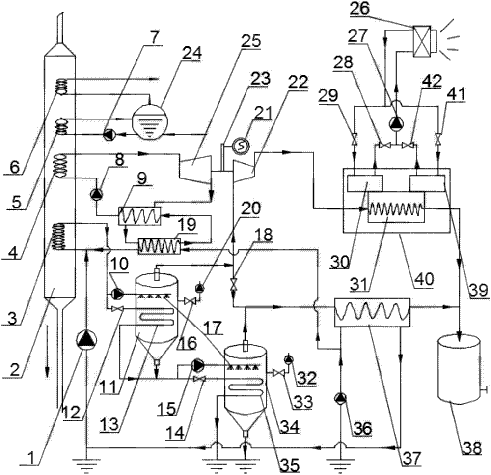
[0031] Such as figure 1 As shown, it is a cascaded use of ship waste heat in an embodiment of the present invention, which includes a waste heat boiler system, an organic working medium Rankine cycle system, an absorption heat pump system, a seawater flash desalination system, and a flue gas desalination system. Gas pipe cavity 2, shaft switcher 23 and generator ...


PUM


Abstract

The invention discloses a ship waste heat step utilization type cold-and-hot electric desalination four-cogeneration device which comprises a waste heat boiler system, an organic working medium Rankine cycle system, an absorption-type heat pump system, a seawater flash evaporation desalination system, a flue gas pipe cavity, a rotating shaft switcher and a generator. The organic working medium Rankine cycle system replaces a low-pressure stage waste heat boiler in a two-stage waste heat boiler system, and thus the heat-power conversion efficiency is effectively improved; the quantity of flue gas waste heat absorbed by seawater flash evaporation is increased, and the freshwater yield is effectively increased; first-stage flash evaporation saturated steam in the seawater flash evaporation desalination system is compressed into superheated steam through a turbine-driven steam compressor to be used for driving an absorption-type heat pump unit to operate; and thus the problem of corrosiondamage due to the fact that flue gas directly enters the absorption-type heat pump unit is effectively avoided while temperature adjustment in a ship cabin is achieved. A waste heat boiler, an organicworking medium Rankine cycle device, a seawater flash evaporation desalination device and an absorption-type heat pump device are matched, and thus the cold-and-hot electric desalination four-cogeneration effect of ship flue gas waste heat 350-80 DEG C step utilization is achieved.

Description

technical field [0001] The invention relates to a cascaded utilization device and working method for waste heat of a ship main engine, in particular to a cascade utilization type cooling, heating, electricity, and desalination quadruple generation device for ship waste heat, which belongs to the technical field of energy engineering. Background technique [0002] At present, in terms of waste heat utilization of ship main engines, two-stage waste heat boilers are mainly used to recover the waste heat of the main engine, and then the waste heat of the ship main engine is converted into electric energy through steam turbines and generators to meet the power demand of ships. As far as the two-stage waste heat boiler is concerned, when the flue gas temperature of the main engine is reduced from 350°C to 120°C, the high-pressure stage waste heat boiler undertakes the main work of thermoelectric conversion, while the low-pressure stage waste heat boiler usually has low efficiency, ...

Claims


Application Information

Patent Timeline
IPC IPC(8): F01K25/08F01K23/10F01D15/08F01D15/10F22B1/18C02F1/06C02F103/08
CPCY02A20/124Y02E20/14Y02E50/10
Inventor 杨兴林李自强崔海滨靳玉冬李俊霞石园园
Owner JIANGSU UNIV OF SCI & TECH
Why Eureka
Try Eureka