Method for recycling water and heat in flue gas discharged by coal-fired power plant and system thereof

A technology for coal-fired power plants and heat recovery, applied in separation methods, feed water heaters, chemical instruments and methods, etc., can solve the problems of limited degree of heating of cooling water, insufficient lift of flue gas, large quantity, etc., so as to reduce water content. , Solve the phenomenon of white smoke, solve the effect of gypsum rain

Inactive Publication Date: 2018-01-09
江苏汇创流体工程装备科技有限公司
View PDF8 Cites 9 Cited by
  • Summary
  • Abstract
  • Description
  • Claims
  • Application Information

AI Technical Summary

Problems solved by technology

[0003] Due to the low temperature of flue gas discharged from coal-fired power plants, it is difficult to recover moisture and heat. At present, some research institutions at home and abroad have used hollow fiber membranes and ceramic membranes to conduct research on the recovery of moisture and heat in flue gas, such as Nanjing University of Technology has studied "a ceramic membrane condensation treatment and recovery method for flue gas waste heat and water in power plants" ZL201310685026.X, North China Electric Power University has studied "a device and method for capturing water vapor in flue gas based on hollow fiber membranes" "ZL201310410548.9, but there are still some problems in the existing research results of these two technologies, and they cannot be commercialized in power plants
Among them, the ceramic membrane recovery technology flows flue gas and cooling water in opposite directions on both sides of the ceramic membrane. Although water can be recovered, it is difficult to realize waste heat utilizati

Method used


Image

  • Method for recycling water and heat in flue gas discharged by coal-fired power plant and system thereof

Examples


Embodiment Construction

[0020] The present invention will be described in further detail below in conjunction with the accompanying drawings and specific embodiments, but the protection scope of the present invention is not limited thereto.

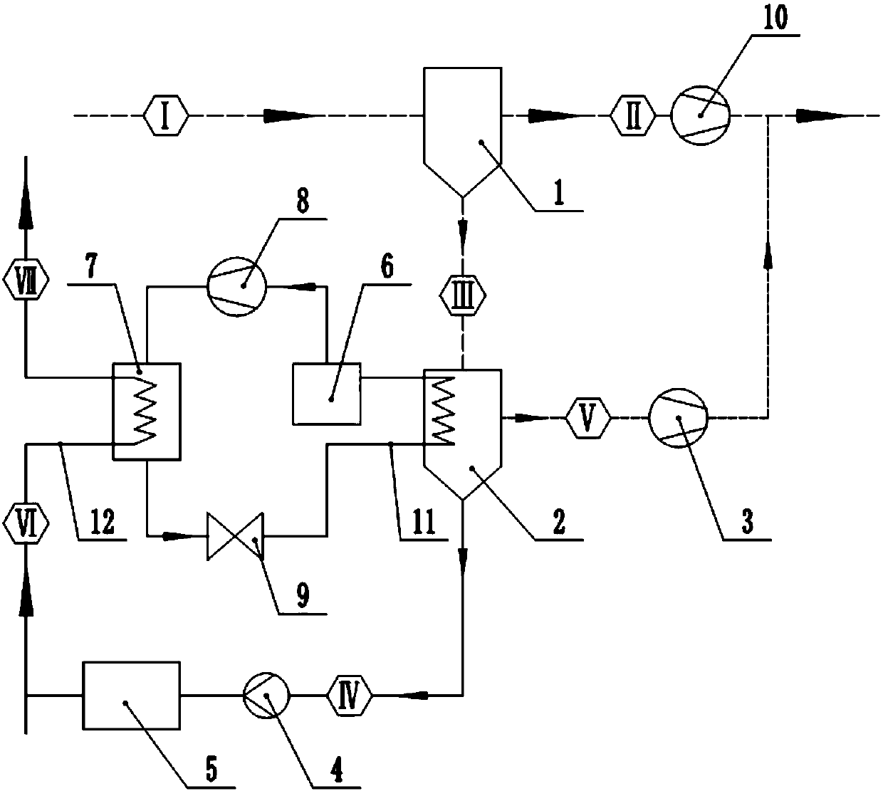
[0021] The specific steps of the moisture and heat recovery and utilization method in the exhaust flue gas of a coal-fired power plant are as follows:

[0022] The membrane module 1 is arranged in the flue between the desulfurization tower and the chimney of the power plant. The membrane module 1 is connected to the inlet of the condenser A2 through a pipeline, and the outlet of one end of the condenser A2 is connected to the boiler circulating water pipeline through a pipeline. The condensate pump 4 and the water purification equipment 5 are sequentially arranged on the pipeline connecting the condenser A2 and the boiler circulating water pipeline; the other end outlet of the condenser A2 is connected with the flue through a pipeline, and a vacuum pump 3 is inst...


PUM


Abstract

The invention discloses a method for recycling water and heat in flue gas discharged by a coal-fired power plant and a system thereof. The method is realized by two systems, namely a hollow fiber membrane water vapor trapping system and a heat pump system. The hollow fiber membrane water vapor trapping system comprises a membrane assembly, a condenser A, a vacuum pump, a condensate water pump andwater purification equipment; the heat pump system comprises an evaporator, a compressor, a condenser B and an expansion valve connected end to end by a heat exchange circulating pipeline A so as to form a circulation loop, and provides a cold source for the hollow fiber membrane water vapor trapping system by condensing the trapped water vapor into water so as to realize water recovery; the hollow fiber membrane water vapor trapping system provides a heat source for the heat pump system for heating boiler circulating water so as to realize heat recovery. According to the method disclosed by the invention, 20-40% of water and heat in the flue gas discharged by the coal-fired power plant can be recycled, and the aims of saving water and energy can be achieved; meanwhile, the parameters of the flue gas discharged by the power plant are improved, and the white smoke phenomenon and gypsum rain problem can be avoided.

Description

technical field [0001] The invention relates to the technical field of water and heat recovery and utilization, in particular to a method and system for water and heat recovery and utilization of flue gas discharged from a coal-fired power plant. Background technique [0002] For coal-fired power plants, due to the installation of wet desulfurization towers, the exhaust gas contains a large amount of saturated water vapor. For a 600MW coal-fired unit, the amount of flue gas discharged at about 50°C per hour is about 200×10 4 N m 3 / h, the saturated water vapor content in the flue gas is about 200t / h, and the latent heat carried by the water vapor is about 1.24×10 8 kcal / h, if the coal-fired unit operates for an average of 5,500 hours per year, the annual discharge of water is about 1.1 million tons, and the annual discharge of heat is equivalent to burning 97,000 tons of standard coal. [0003] Due to the low temperature of flue gas discharged from coal-fired power plants...

Claims


Application Information

Patent Timeline
IPC IPC(8): B01D53/00B01D53/22F22D1/00F22D11/06F23J15/00
Inventor 翟欢乐王勇陆军刘敏阚亚雄邓春萌陆荣阮小婷
Owner 江苏汇创流体工程装备科技有限公司
Why Eureka
Try Eureka