

Technology and system for catalytic cracking
A catalytic cracking and process technology, which is applied in the process and system field of catalytic cracking, can solve the problems of insignificant conversion rate of heavy oil and decrease of dry gas yield, so as to improve the conversion rate of heavy oil, slow down the yield of dry gas and coke , to promote the effect of cracking again
- Summary
- Abstract
- Description
- Claims
- Application Information
AI Technical Summary
Problems solved by technology
Method used
Image

Examples
Embodiment approach
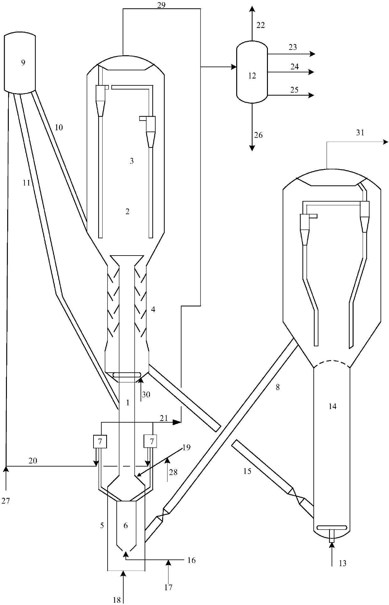
[0058] A specific embodiment, the lower part of the riser reaction section is provided with a heavy raw material inlet, and the bottom of the first fluidized bed reactor 6 is provided with a first fluidized bed reaction system for feeding regenerated catalyst and light raw materials. The lower part of the pre-lift section 5 is provided with a regenerated catalyst inlet, and the regenerated catalyst inlet is in fluid communication with the riser reaction section and the first fluidized bed reactor inlet through the gap.
[0059] In order to facilitate the separation of products and the regeneration of the spent catalyst, the system also includes a settling section 3 above the second fluidized bed reactor 2 and a stripping section below the second fluidized bed reactor 2 4. The riser reactor 1 extends into the stripping section 4 and the dense-bed reactor 2 from below the stripping section 4, and the top outlet of the riser reactor 1 is located in the The lower part of the dense...
Embodiment 1
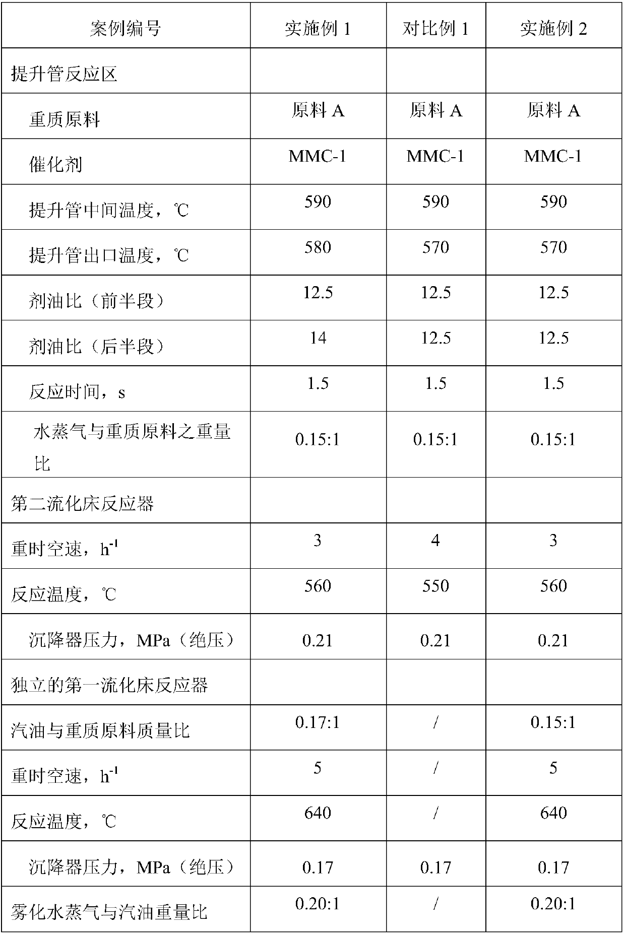
[0071] test in as figure 1It is carried out in the medium-sized catalytic cracking unit shown. The device includes a set of independent reaction regeneration system and riser reactor plus fluidized bed combination reactor. The inner diameter of the riser reaction zone is 16 mm and the length is 3200 mm. After the riser reaction zone, the second fluidized bed reaction is connected in series. The second fluidized bed reactor has a diameter (inner diameter) of 64 mm and a height of 600 mm. Used catalyzer is MMC-2 catalyzer, carries out the second catalytic cracking and the 3rd catalytic cracking to the raw material shown in table 1 successively, the 3rd product after cracking is separated with the 3rd standby catalyst, the 3rd standby catalyst enters stripping After stripping, it enters the regenerator for regeneration, and the regenerated regenerated catalyst returns to the pre-lift section of the riser for recycling; the third product is introduced into the product separation ...
Embodiment 2
[0075] With reference to Example 1, the difference is that the high-temperature catalyst in the catalyst buffer tank is imported into the second fluidized bed reactor through the catalyst pipeline to increase the reaction temperature of the second fluidized bed reactor, and its reaction operating conditions and reaction results are shown in the table 3 and Table 4.
[0076] It can be seen from Table 3 and Table 4 that an independent first fluidized bed reactor is set up in the pre-lifting section, and the high-temperature catalyst in the pre-lifting section is used to compensate for the endothermic heat in the reaction process, which can ensure a constant temperature in the entire reactor. The reaction environment improves the conversion rate of gasoline injected into the first fluidized bed reactor, and increases the yield of light olefins. The high-temperature first spent catalyst from the independent first fluidized bed reactor is lifted into the catalyst buffer tank, and t...
PUM
| Property | Measurement | Unit |
|---|---|---|
| The inside diameter of | aaaaa | aaaaa |
| Height | aaaaa | aaaaa |
Abstract
Description
Claims
Application Information