Graphene spontaneous heating floor, manufacturing method and low-voltage spontaneous heating floor system

A graphene and self-heating technology, applied in the field of building decoration materials, can solve problems such as energy waste, inability to effectively meet the use needs, and traditional home building materials that cannot meet consumer decoration needs, etc., to achieve rapid heating, prolong the service life, and reduce energy consumption. The effect of consumption

Active Publication Date: 2018-01-26
戴明
View PDF9 Cites 11 Cited by
  • Summary
  • Abstract
  • Description
  • Claims
  • Application Information

AI Technical Summary

Problems solved by technology

The existing heating floor can only realize all-round temperature control and shutdown according to the needs of the human body for indoor temperature, and cannot realize independent temperature control of the heating floor for specific groups of people, specific locations and specific needs. Usage r

Method used


Image

  • Graphene spontaneous heating floor, manufacturing method and low-voltage spontaneous heating floor system
  • Graphene spontaneous heating floor, manufacturing method and low-voltage spontaneous heating floor system
  • Graphene spontaneous heating floor, manufacturing method and low-voltage spontaneous heating floor system

Examples


Embodiment 1

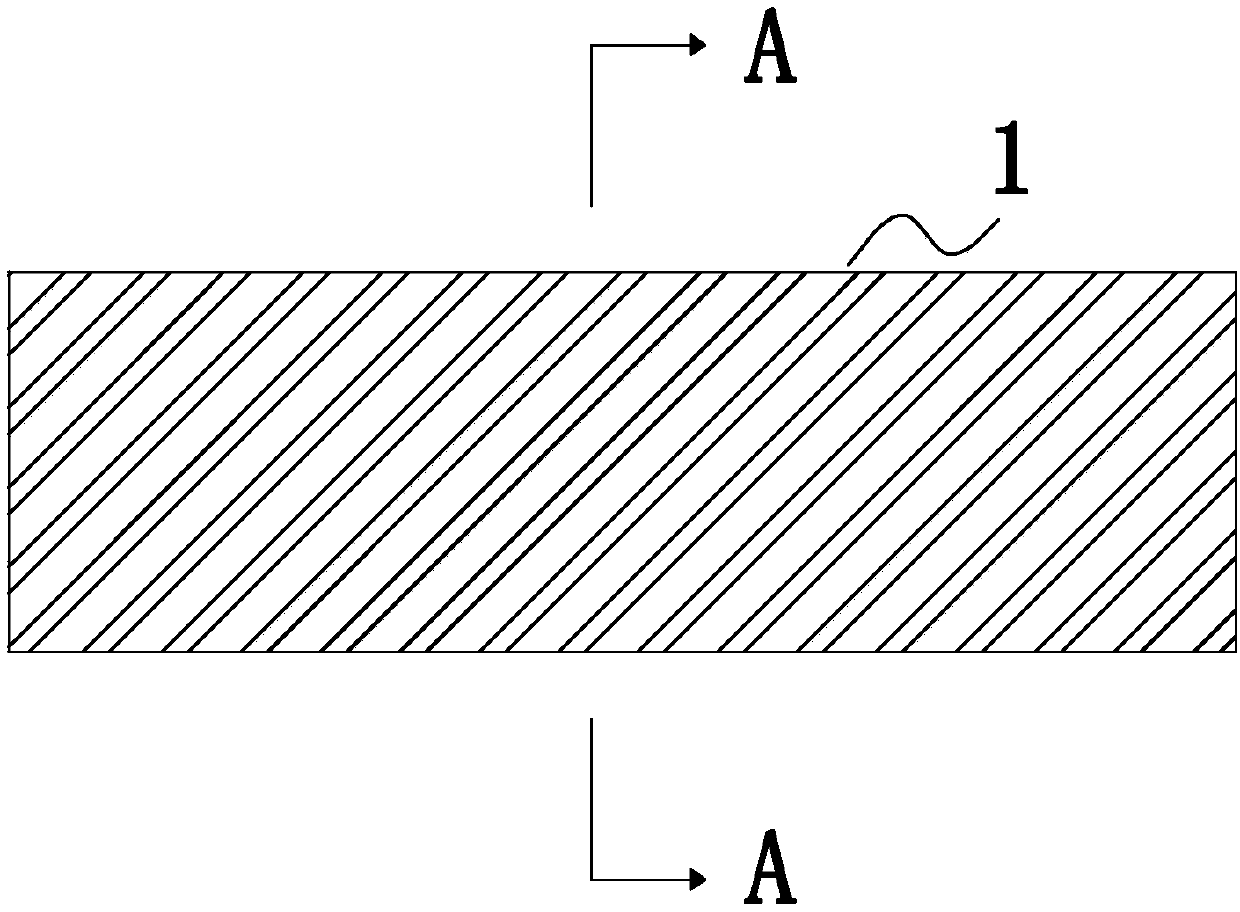
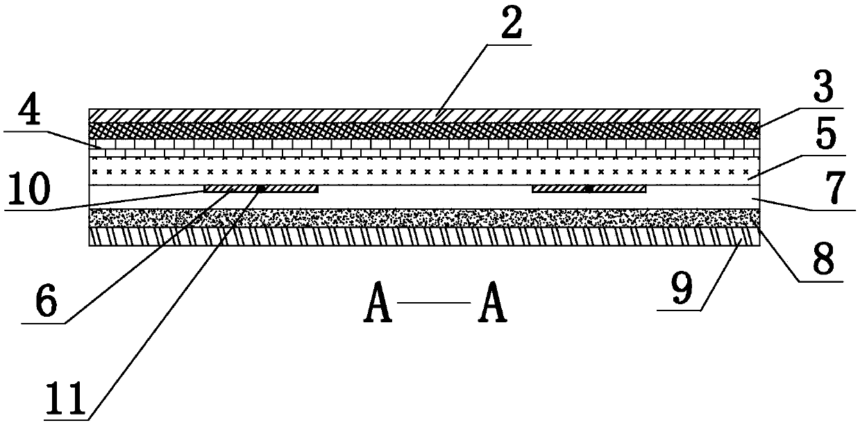
[0046] figure 1 It is a top view of a graphene self-heating floor; figure 2 for figure 1 longitudinal section view. Such as figure 1 , figure 2 As shown, a graphene self-heating floor includes a floor body 1, and the floor body 1 sequentially includes a closely fitted wear-resistant layer 2, a surface decoration layer 3, an upper insulating flame-retardant, temperature-resistant and waterproof layer 4, an upper The substrate plate layer 5, the lower substrate plate layer 7, the lower insulation, flame-retardant, temperature-resistant and waterproof layer 8 and the heat preservation layer 9.

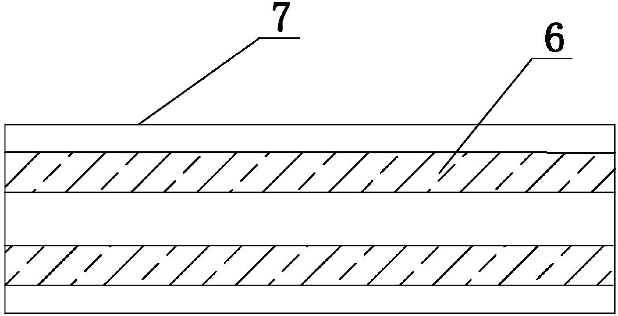
[0047] The upper surface of the lower substrate ply 7 is provided with at least one groove 10 whose groove depth is smaller than the thickness of the lower substrate ply 7, and the two ends of the groove 10 pass through the lower substrate ply 7, such as image 3 shown. A graphene heating element 6 is laid in the groove 10, and a conductive circuit 11 closely attached to the graph...

Embodiment 2

[0073] Embodiment 2 provides a more preferred graphene self-heating floor structure on the basis of embodiment 1. Specifically, this embodiment 2 further defines:

[0074] Wear-resistant layer 2 is made of surface paper impregnated with melamine resin added with aluminum oxide, which is a key part of determining the life of laminate flooring. The wear-resistant layer endows the surface of laminate flooring with important physical and chemical properties such as wear resistance, scratch resistance, cigarette burning resistance, pollution resistance, corrosion resistance, and moisture resistance.

[0075] The surface decoration layer 3 is any one of melamine decorative paper, PVC board, fireproof board, and decorative wood veneer. After the surface of the board layer is processed by three methods of machining, veneer decoration or painting, the three-dimensional effect of the board surface is increased. , special performance and aesthetics.

[0076] Both the upper insulating fl...

Embodiment 3

[0081] Embodiment 3 On the basis of Embodiment 1, a more preferred graphene self-heating floor structure is provided. Specifically, this Embodiment 3 further defines that the number of grooves 10 is 2n, wherein n is a natural number , and the sum of the widths of the 2n grooves 10 is smaller than the longitudinal width of the lower base plate layer 7 . The graphene heating element 6 releases a large amount of heat energy after being energized and excited. In order to ensure that the floor absorbs heat evenly, it is further preferred that the grooves 10 are symmetrically distributed along the central axis of the lower substrate layer 7 in the transverse direction. Also in order to ensure that the magnetic field is evenly released, and to control the magnetic force of the magnetic field to suit the needs of the human body, it is further preferred that the center of the blind hole 13 coincides with the central axis in the transverse direction of the upper substrate plate 5, and th...


PUM

PropertyMeasurementUnit
Thicknessaaaaaaaaaa
Densityaaaaaaaaaa
Thicknessaaaaaaaaaa

Abstract

The invention provides a graphene spontaneous heating floor, a manufacturing method and a low-voltage spontaneous heating floor system. The graphene spontaneous heating floor sequentially comprises anabrasion resisting layer, a surface decoration layer, an upper insulation inflaming retarding and temperature resisting waterproof layer, an upper base material floor layer, a lower base material floor layer, a lower insulation inflaming retarding and temperature resisting waterproof layer and a heat insulation layer from top to bottom. The upper surface of the lower base material floor layer isprovided with at least one groove. The grooves are internally paved with graphene heating elements and conducting circuits. The two ends of each conducting circuit are connected with connector clips.The connector clips of each conducting circuit are both connected with an independent control unit. The upper surface of the upper base material floor layer is provided with a plurality of blind holes, and magnet columns are embedded into the blind holes. The graphene spontaneous heating floor has the beneficial effects that a graphene material is adopted for conducting heat, the temperature is raised quickly, and heat conduction is uniform; and each floor is an intelligently-integrated independent unit, zone control of the indoor temperature is achieved, the energy consumption is reduced, andthe service life of the floor is prolonged; and graphene releases far infrared rays, by cooperating with the magnet therapy characteristics of magnets, the graphene spontaneous heating floor strengthens the physical body, protects health and is beneficial to family health.

Description

technical field [0001] The invention belongs to the field of building decoration materials, in particular to a graphene self-heating floor, a manufacturing method and a low-voltage self-heating floor system. Background technique [0002] In the cold winter, equipment such as heaters and heating are usually used indoors to create a warm environment for the home. However, when the furnace and heating are in operation, there are often reports of users being accidentally scalded, and it is very easy to cause occupants to slip accidentally and get injured, which often poses a safety hazard. In addition, the stove and heating take up indoor space, reducing the effective use area of ​​the house. At the same time, the heat in the house is uneven, and the temperature around the stove and heating is high, while the temperature in places far away from the stove and heating is low, and the occupants feel uncomfortable. In recent years, as the research on floor heating equipment has bec...

Claims


Application Information

Patent Timeline
IPC IPC(8): F24D13/02H05B3/14H05B3/28E04F15/10E04F15/18
CPCH05B3/14H05B3/28E04F15/10E04F15/18F24D13/02Y02B30/00
Inventor 戴明
Owner 戴明
Why Eureka
Try Eureka