Micro-cathode electric arc thruster

A cathodic arc and cathode technology, which is applied in thrust reversers, machines/engines, propulsion systems for space vehicles, etc., can solve the problems of inconvenient integration of micro-nano satellite operating systems, safety to be further improved, and high plasma energy consumption. , to achieve the effect of easy quantitative production, simple structure and high pulse stability

Inactive Publication Date: 2018-02-02
HARBIN INST OF TECH SHENZHEN GRADUATE SCHOOL
View PDF7 Cites 15 Cited by
  • Summary
  • Abstract
  • Description
  • Claims
  • Application Information

AI Technical Summary

Problems solved by technology

[0009] The size of the existing technical solution is large, it cannot generate the ideal thrust, and it is not convenient to integrate into the operating system of the micro-nano sat

Method used


Image

  • Micro-cathode electric arc thruster
  • Micro-cathode electric arc thruster

Examples


Example Embodiment

[0036] Embodiment 1 A kind of micro-cathode arc thruster

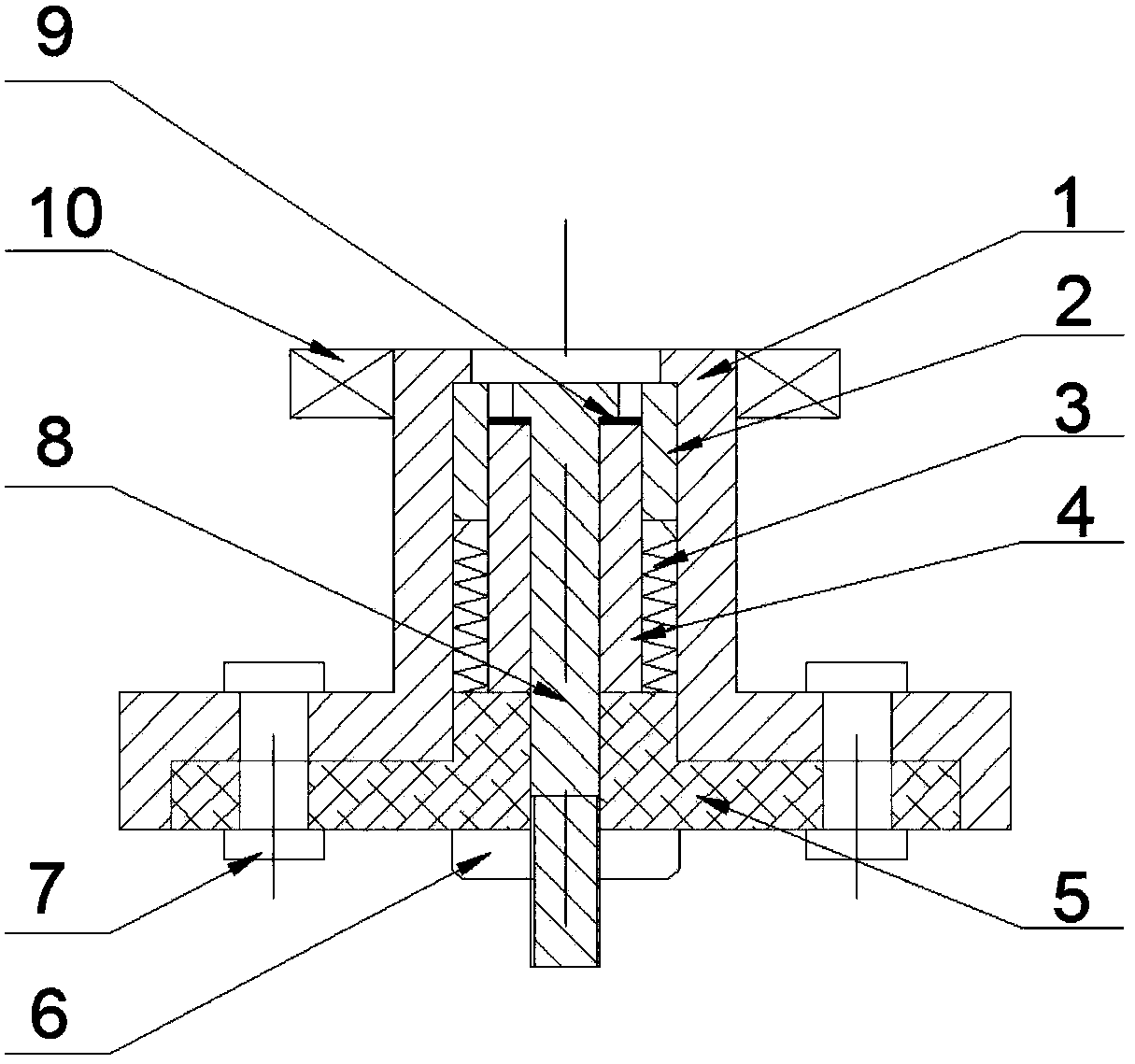
[0037] refer to figure 1 and 2 As shown, the micro-cathode arc thruster is a tubular annular structure as a whole, wherein the shell 1 and the base 5 are connected to form a semi-closed cylindrical structure; the ceramic cylinder 4 is arranged in the semi-closed cylindrical structure, and the base 5 ceramic cylinder 4 An insulating structure is formed to isolate the anode and cathode; the cathode working medium 2 is connected to the casing 1 to form a cathode path, together with the anode 8 and the conductive coating layer 9 set on the top of the ceramic cylinder 4 form a complete conductive circuit, the conductive coating layer 9 is before arcing Flow resistance, access in working state; spring 3 is placed at the lower end of cathode 2, and the lower end of spring 3 is connected to base 5, and the working medium propulsion system is mainly completed by spring 3; the connection between cathode working medium 2 and she...

Example Embodiment

[0038] Embodiment 2 A kind of micro-cathode arc thruster

[0039] refer to figure 1 and 2 As shown, on the basis of Example 1, the cathode working medium 2 is in the shape of a circular through-hole, which doubles as a propellant working medium, and its material can be conductive metal materials such as copper, nickel, and titanium.

[0040] The conductive coating layer 9 is coated on the side of the ceramic cylinder 4 close to the magnetic coil 10 and is in the shape of a ring. The conductive coating layer can be a functional conductive film layer such as titanium nitride, carbon, or titanium carbide nitride.

[0041] The base 5 is in the shape of a cylindrical boss, and the upper part cooperates with the inner hole of the shell 1. It adopts insulating materials such as Teflon, and is combined with the shell to close the internal structure. The middle hole is used for the anode rod 8 to pass through.

[0042] The anode 8 is rod-shaped, and the outer diameter of the upper bo...


PUM


Abstract

The invention belongs to the field of electric thrust and particularly relates to a micro-cathode electric arc thruster applied to a micro-nano satellite. The micro-cathode electric arc thruster is mainly applied to power systems of small satellites such as the micro-nano satellite. According to the micro-cathode electric arc thruster, aiming at solving the problem that an existing micro-nano satellite is not provided with a propelling system, through the vacuum cathodic electric arc discharging principle, an integral electric thruster structure is designed. The thruster structure is mainly composed of a shell 1, a cathodic working medium 2, a spring 3, a ceramic cylinder 4, a base 5, fixing nuts 6, nut fastening bolts 7, an anode 8, a conductive coating film layer 9 and a magnetic coil 10. When a preset voltage is achieved between a cathode and the anode, cathode spots conduct discharging, spreading is gradually conducted, and the cathodic working medium is continuously subjected to ionization corrosion to form a stable plasma plume. The plasma plume is sprayed outwards under the effect of an applied magnetic field to form needed counteractive thrust. The micro-cathode electric arc thruster is small in overall structural size and low in weight.

Description

technical field [0001] The invention belongs to the field of electric thrust, and more specifically relates to a micro-cathode arc thruster applied to micro-nano satellites. Background technique [0002] With the continuous advancement of technology and the gradual reduction of technical thresholds, the micro-nano satellite industry is gradually emerging around the world. Micro-nano satellite technology is considered to be the most technologically and commercially promising aerospace technology in the 21st century. It is not only an important strategy for military defense Meaning, it will also have a revolutionary impact on many industries in business, such as communication, Internet, agriculture, education and medical care and other industries. Micro-nano satellites are no longer products that can only be produced by large or giant state-owned enterprises. Many private companies and even individual entrepreneurial teams are involved. [0003] Micro-nano satellites have a s...

Claims


Application Information

Patent Timeline
IPC IPC(8): B64G1/40F03H1/00
Inventor 曹勇楚豫川何兆国杨智
Owner HARBIN INST OF TECH SHENZHEN GRADUATE SCHOOL
Why Eureka
Try Eureka