
Flight parameter signal generating system

A signal generation and flight parameter technology, applied in the field of flight parameter signal generation system, can solve the problems of uncontrollable progress, unrealistic, expensive airborne equipment, etc., achieve strong anti-interference ability, low power consumption, and high operating speed Effect

Inactive Publication Date: 2018-02-06
HENAN POLYTECHNIC UNIV
View PDF2 Cites 6 Cited by
  • Summary
  • Abstract
  • Description
  • Claims
  • Application Information

AI Technical Summary

Problems solved by technology

In order to ensure the quality of the flight parameter recorder produced, it is necessary to use the real flight parameter data signal as the test signal in the process of development, improvement, debugging, maintenance and verification, but in practice, the airborne equipment is expensive, and the flight parameter recorder Due to factors such as the uncertainty of the development cycle and the uncontrollability of the progress, it is difficult and unrealistic to use a real aircraft to provide a test signal source for the development of the flight parameter recorder during the development process.

Method used


Image

  • Flight parameter signal generating system
  • Flight parameter signal generating system
  • Flight parameter signal generating system

Examples


Embodiment Construction

[0015] The present invention will be described in detail below in conjunction with the accompanying drawings and specific embodiments.

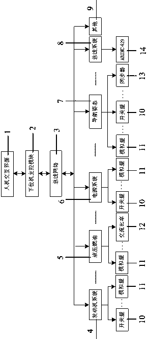
[0016] A flight parameter signal generation system of the present invention includes: a human-computer interaction interface of a host computer and a signal generation system of a lower computer, the structure of which is as follows figure 1 As shown, the human-computer interaction interface is the upper computer 1, and the lower computer signal generation system includes the engine system module 4, the hydraulic fuel system module 5, the power system module 6, the navigation attitude system module 7, the bus system module 8 and other modules 9. Using LabVIEW to design and develop the human-computer interaction interface 1 of the upper computer, select the Access database to store the parameter data set by the upper computer, use the STM32 as the main control module 2 and combine the RS485 bus 3 to build the communication network of the lower ...


PUM


Abstract

The invention discloses a flight parameter signal generating system. The system includes an upper computer man-machine interaction interface and a lower computer signal generating system, wherein thelower computer signal generating system includes an engine system module, a hydraulic pressure fuel oil system module, a power system module, a navigation attitude system module, a bus system module and the like. LabVIEW is adopted for designing the upper computer man-machine interaction interface, an Access database is selected for storing parameter data set by an upper computer and a lower computer communication network is constructed by taking an STM32 as a main control module in combination with RS485 technology. Switching quantity signals are achieved by adopting a single-chip microprocessor in combination with a photovoltaic coupler. Analog quantity signals are generated through controlling a DAC chip by the single-chip microprocessor. AC rate signals are generated through an AC ratetable. Generation of synchronizer signals is realized through a chip AD9959. Generation of ARINC429 is realized through controlling HS-3182 and HS-3282 by the single-chip microprocessor. Generation of AC power signals is realized through a voltage transformer. A DC power supply power source is achieved through a voltage stabilizing chip. Flight parameters are allocated to different signal generation modules. On one hand, management is facilitated. On the other hand, design margin is realized and addition and reduction of signal generation modules are facilitated.

Description

technical field [0001] The invention belongs to the technical field of aviation test equipment, and relates to a flight parameter signal generating system. Background technique [0002] The flight parameter recorder, commonly known as the black box, is an airborne device used to record the status information of the various components of the aircraft during flight. Its exterior is wrapped in a metal box that is corrosion-resistant, fire-resistant, and impact-resistant, and it can still be preserved intact after the aircraft crashes. , so the black box is widely used in aviation vehicles such as airplanes. The flight parameter recorder is mainly used to record various data of the aircraft during flight, including engine system, control system, hydraulic fuel system, power supply system, navigation attitude, radio system, environmental control system, anti-icing system and fire extinguishing system, etc. Hundreds of parameter data can store the latest flight parameter data of ...

Claims


Application Information

Patent Timeline
IPC IPC(8): G05B19/042
CPCG05B19/0423G05B2219/21071
Inventor 赵彦如王东升王耿李长有野贵荣
Owner HENAN POLYTECHNIC UNIV
Learn More