
Direct sequence/frequency hopping signal system array antenna adaptive beamforming system

An adaptive beam and array antenna technology, applied in transmission systems, electrical components, etc., can solve the problems of insufficient anti-interference, anti-interception, and anti-receipt capabilities, and achieve improved anti-interference capabilities, strong anti-interference capabilities, and enhanced anti-interference capabilities. the effect of interference

Inactive Publication Date: 2018-02-06
10TH RES INST OF CETC
View PDF5 Cites 35 Cited by
  • Summary
  • Abstract
  • Description
  • Claims
  • Application Information

AI Technical Summary

Problems solved by technology

[0007] Aiming at the serious shortage of anti-jamming, anti-interception and anti-detection capabilities of traditional shooting range measurement and control systems, the present invention provides a device with strong anti-interference ability, which can enhance the anti-interference, anti-detection and anti-reception capabilities of the shooting range measurement and control system in complex electronic environments. Array Antenna Adaptive Beamforming System with Spreading / Frequency Hopping Signal System Capable of Intercepting "Three Resistances"

Method used


Image

  • Direct sequence/frequency hopping signal system array antenna adaptive beamforming system
  • Direct sequence/frequency hopping signal system array antenna adaptive beamforming system
  • Direct sequence/frequency hopping signal system array antenna adaptive beamforming system

Examples


Embodiment Construction

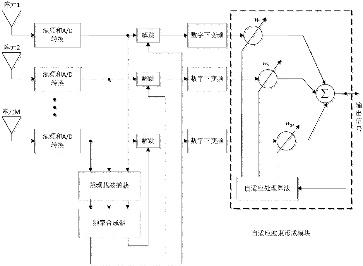
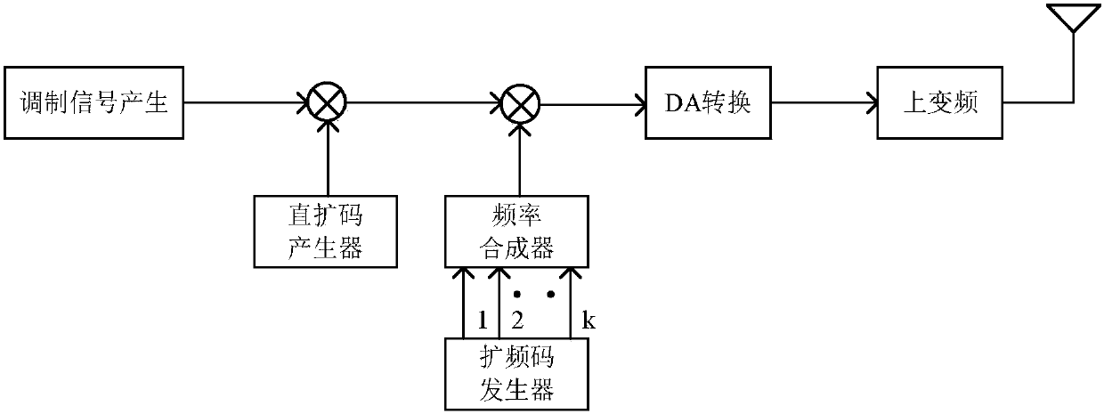
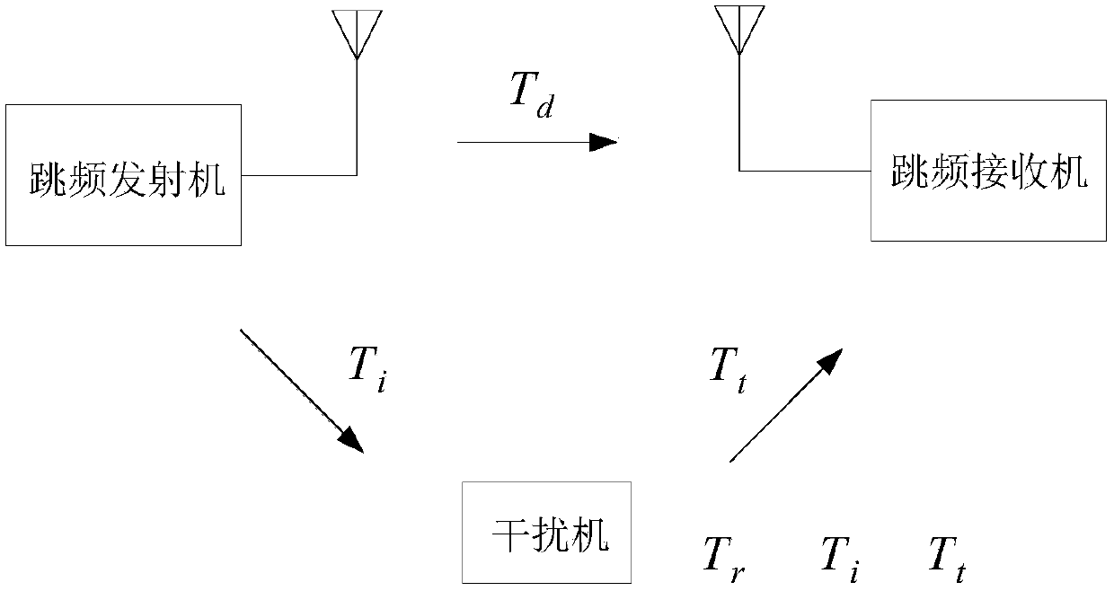
[0019] refer to figure 1 . In the embodiment described below, an array antenna adaptive beamforming system includes: a frequency hopping transmitter, a jammer, M array element antennas for receiving radio frequency signals, and an electrical connection between the M array element antennas and digital down-conversion The frequency mixer and the A / D converter between the devices are characterized in that: at the direct spread-frequency hopping DS-FH signal sending end, the frequency hopping transmitter adopts the DS-FH hybrid output of the DS-FH hybrid spread spectrum measurement and control system The spread spectrum signal passes through each element channel of the array antenna, mixes the received radio frequency signal through the mixer and the A / D converter, A / D converts it into a digital signal, and the digital signal is captured by a frequency synthesizer frequency hopping carrier The output reference local oscillator signal is mixed to realize the dehopping of the RF DS...


PUM


Abstract

The invention discloses a direct sequence / frequency hopping signal system array antenna adaptive beamforming system. The adaptive beamforming system has strong anti-jamming capability. According to the technical schemes of the invention, DS-FH (direct sequence / frequency hopping) mixed spread spectrum signals outputted by a frequency hopping transmitter pass through each array element channel of anarray antenna; mixers mix received radio frequency signals; A / D converters convert mixed signals into digital signals; the digital signals are subjected to frequency hopping carrier capturing, and then, a frequency synthesizer outputs reference local oscillation signals in a mixed manner; the de-hopping of the radio frequency DS-FH signals is realized; de-hopped direct sequence spread spectrum signals are subjected to primary down-conversion through digital down converters; a plurality of paths of intermediate-frequency direct sequence spread spectrum signals which are obtained after digitaldown-conversion is performed are sent to an adaptive beamforming module; the adaptive beamforming module generates a path of spread spectrum signals through weighting; the adaptive beamforming moduleperforms de-spreading processing on the spread spectrum signals; a weight vector is solved through adopting a recursive least squares (RLS) algorithm; minimum output power is obtained according to theobtained weight vector; and nulls at interference sites are formed.

Description

technical field [0001] The invention relates to an array antenna self-adaptive beam forming system of a spread / frequency hopping signal system applied in a shooting range measurement and control system. Background technique [0002] Direct Sequence Spread Spectrum-DSSS (Direct Spread-DS for short) and Frequency Hopping Spread Spectrum-FHSS (FHSS for short) are the most widely used in these two fields. spread spectrum method. Due to the low spectral density of the pseudo-code direct sequence spread spectrum system, it has good anti-interference and anti-intercept performance, and its application in engineering is becoming more and more common. In foreign countries, the ultra-wideband spread spectrum technology is more popular, and its characteristics are as follows: Good concealment, strong penetrating ability, high spreading gain, anti-multipath, high transmission rate, large system capacity, easy networking, high positioning accuracy, etc. It is easy to integrate positioni...

Claims


Application Information

Patent Timeline
IPC IPC(8): H04B1/713H04B1/7136H04B1/715H04B1/719H04B1/707
CPCH04B1/713H04B1/707H04B1/7136H04B1/715H04B1/719
Inventor 刘明凯蒋宇志张旭吴述敏陈文兵
Owner 10TH RES INST OF CETC
Learn More