Lithium Complex Oxide For Lithium Secondary Battery Positive Active Material And Method Of Preparing The Same

A composite oxide, lithium secondary battery technology, used in secondary batteries, lithium storage batteries, chemical instruments and methods, etc., can solve the problems of high LiOH viscosity, decreased capacity and rate characteristics, and surface damage of positive active materials.

Active Publication Date: 2018-02-09
ECOPRO BM CO LTD
6 Cites 0 Cited by

AI-Extracted Technical Summary

Problems solved by technology

[0006] However, since the Ni rich system (Ni rich system) with a Ni content of 65% or more is a low-temperature reaction, it has the ability to form LiOH, Li on the surface of the positive electrode active material 2 CO 3 The problem of high residual lithium in the form
This residual lithium, that is, unreacted LiOH and Li 2 CO 3 Reacts with the electrolyte in the battery, causing gas generation and expansion, which leads to a serious decrease in high temperature safety
In addition, when the slurry is mixed before the preparation ...

Abstract

Disclosed is a lithium complex oxide and method of manufacturing the same, more particularly, a lithium complex oxide effective in improving the characteristics of capacity, resistance, and lifetime with reduced residual lithium and with different interplanar distances of crystalline structure between a primary particle locating in a internal part of secondary particle and a primary particle locating on the surface part of the secondary particle, and a method of preparing the same.

Application Domain

Cell electrodesLi-accumulators +1

Technology Topic

Analytical chemistry

Image

  • Lithium Complex Oxide For Lithium Secondary Battery Positive Active Material And Method Of Preparing The Same
  • Lithium Complex Oxide For Lithium Secondary Battery Positive Active Material And Method Of Preparing The Same
  • Lithium Complex Oxide For Lithium Secondary Battery Positive Active Material And Method Of Preparing The Same

Examples

  • Experimental program(12)
  • Comparison scheme(9)

Example Embodiment

[0066] Preparation of positive electrode active material
[0067] First, NiCo(OH) is prepared by co-precipitation reaction 2 Precursor. Add Li to the prepared precursor 2 CO 3 LiOH and LiOH are used as lithium compounds, and Al and Mg are added as M1, and then the first heat treatment is performed to prepare a positive electrode active material for lithium secondary batteries.
[0068] Prepare distilled water, put the prepared positive active material for lithium secondary battery into the distilled water, and wash the prepared positive active material for lithium secondary battery while maintaining the temperature.
[0069] Then, 0.03 moles of cobalt sulfate aqueous solution was poured into the positive active material washing solution in a certain proportion while stirring the positive active material for 1 hour to coat and wash the surface of the positive active material with Co as M2 , And then dried at 120 ℃ under vacuum conditions.
[0070] Ti was added as M3 to the positive electrode active material with the coating layer, and the second heat treatment was performed at 450° C. to prepare the positive electrode active material for lithium secondary batteries.
[0071] TEM and EDX measurement
[0072] The TEM and EDX photos of the positive electrode active material prepared in Example 1 were measured, and the measurement results are shown in figure 2.
[0073] Such as figure 2 As shown, for the positive electrode active material prepared in Example 1 of the present invention, the Co concentration on the surface of the secondary particles is relatively high, the Co concentration gradually decreases from the surface of the secondary particles to the inside, and the Co concentration is in a gradient in the secondary particles. Distribution, not constant.
[0074] Measurement of interplanar spacing of crystal structure
[0075] For the primary particles located inside the secondary particles of the positive active material prepared in Example 1, and the primary particles located on the surface with the Co and Ti coatings formed, the diffraction pattern and the interplanar spacing were measured, and the measurement results are shown in image 3.
[0076] Such as image 3 As shown, the thickness of the Co coating is about 80nm, and the diffraction pattern of the primary particle located inside the secondary particle is a hexagonal crystal structure. For the primary particle located inside the secondary particle, there are 10 adjacent crystals in the TEM photograph. The average measurement of the interplanar distance was 4.88 nm. On the other hand, the diffraction pattern of the primary particles on the surface on which the Co coating layer was formed had a hexagonal crystal structure, and the interplanar distance was measured to be 4.73 nm.
[0077] It can be seen that, compared with the primary particles located inside the secondary particles without the cobalt coating, the interplanar spacing of the primary particles on the surface is reduced, and the interplanar spacing of the primary particles on the surface is reduced to that of the comparative example. LiCoO 2 The interplanar spacing is similar.

Example Embodiment

[0078] Preparation of positive electrode active material
[0079] The positive electrode active material of Example 2 was prepared by performing the washing and coating processes the same as the above-mentioned Example 1, except that a 4 mol% cobalt aqueous solution was added to the washing solution of the positive electrode active material.
[0080] TEM and EDX measurement
[0081] The TEM and EDX photos of the positive electrode active material prepared in Example 2 were measured, and the measurement results are shown in Figure 4.
[0082] Such as Figure 4 As shown, for the positive electrode active material prepared in Example 2 of the present invention, the Co concentration on the surface of the secondary particles is relatively high, and the Co concentration gradually decreases toward the inside of the secondary particles in a gradient distribution, rather than being constant.
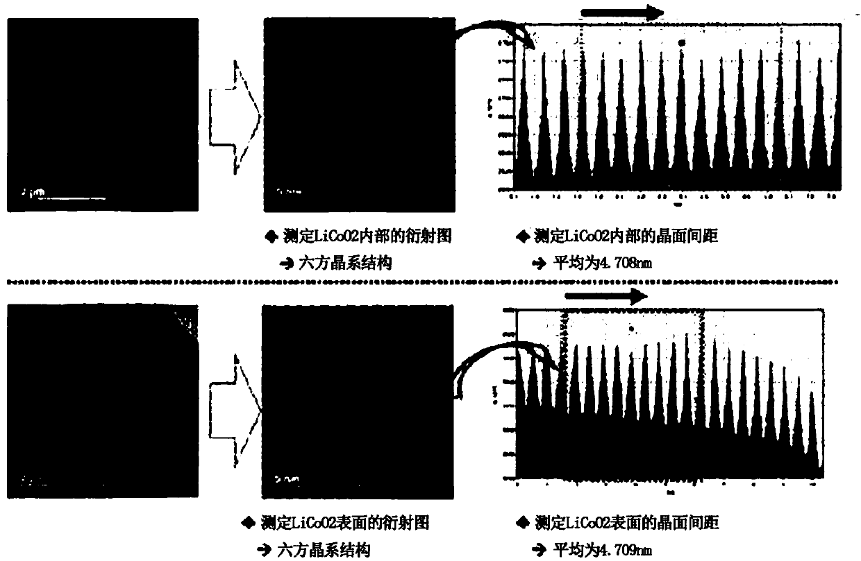
[0083] Measurement of interplanar spacing of crystal structure
[0084] For the primary particles located inside the secondary particles of the positive electrode active material prepared in Example 1, and the primary particles located on the surface with the Co and Ti coatings formed, the diffraction pattern and the interplanar spacing were measured, and the measurement results are shown in Figure 5.
[0085] Such as Figure 5 As shown, the thickness of the Co coating is about 90 nm, and the diffraction pattern of the primary particles located inside the secondary particles is a hexagonal crystal structure. For the primary particles located inside the secondary particles, there are 10 adjacent crystals in the TEM photograph. The average measurement of the interplanar distance was 4.85 nm. On the other hand, the diffraction pattern of the primary particles on the surface on which the Co coating layer was formed had a hexagonal structure, and the interplanar distance was measured to be 4.73 nm.
[0086] It can be seen that the interplanar spacing of the primary particles on the surface is reduced compared with the primary particles located inside the secondary particles without the cobalt coating, and the interplanar spacing of the primary particles on the surface is changed to that of the comparative example. LiCoO 2 The interplanar spacing is similar.

Example Embodiment

[0087] Preparation of NCM-based positive electrode active material
[0088] The positive electrode active material of Example 3 was prepared in the same manner as the above-mentioned Example 1, except that a 5 mol% cobalt aqueous solution was added to the washing solution of the positive electrode active material for coating.
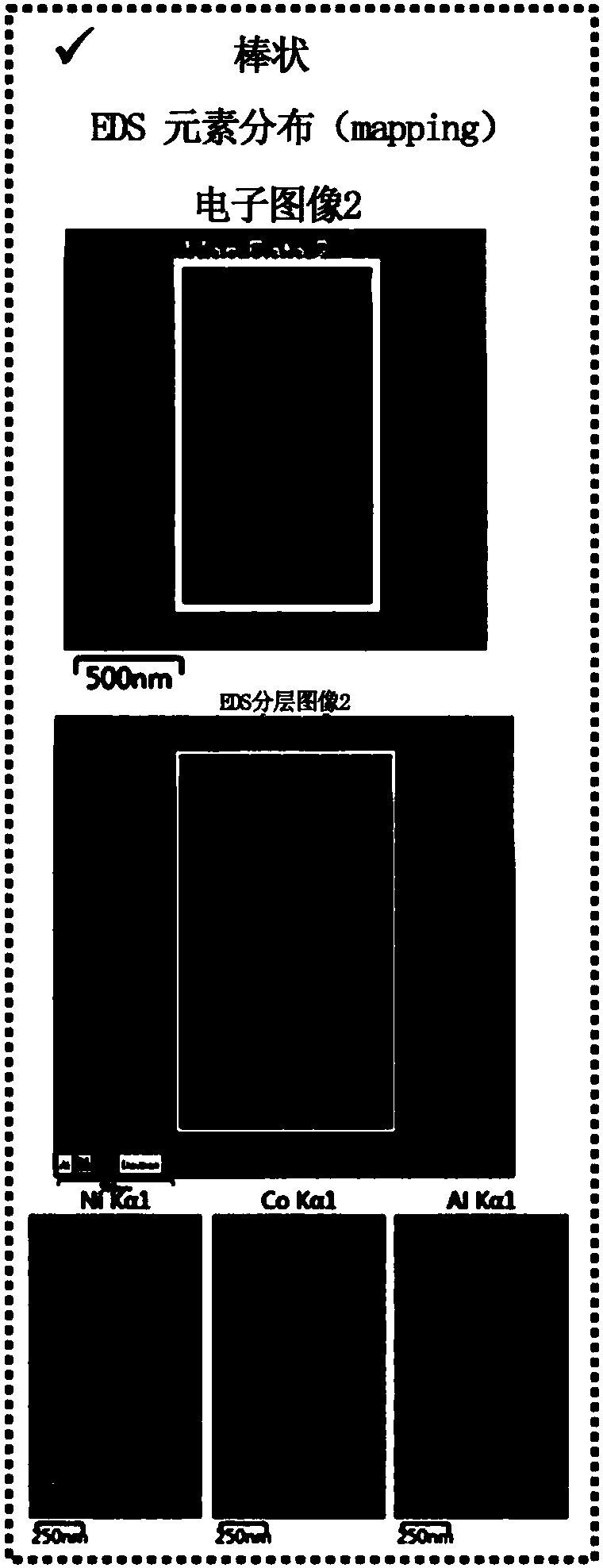
[0089] Scanning concentration
[0090] The changes in the concentrations of Ni, Co, and Al in the positive electrode active material prepared in Example 3 from the surface of the secondary particle to the center of the particle were measured, and the measurement results are shown in Image 6.
[0091] From Image 6 It can be seen that for the positive electrode active material prepared in Example 3 of the present invention, the Co concentration on the Co coating gradually increases from the surface to the center direction, but then the Co concentration gradually decreases toward the center direction, and the thickness of the Co coating is 0.1 μm.
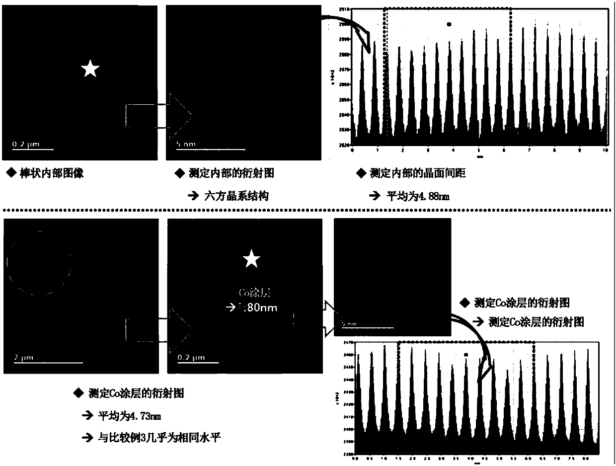
[0092] TEM and EDX measurement
[0093] The EDX photographs of Ni, Co and Al in the positive electrode active material prepared in Example 3 were measured from the surface of the secondary particle to the center of the particle. The measurement results are shown in Figure 7.
[0094] From Figure 7 It can be seen that for the positive electrode active material prepared in Example 3 of the present invention, the Co concentration on the Co coating gradually increases from the surface to the center direction, but then the Co concentration gradually decreases toward the center direction, and along the interface of the primary particle Co. The concentration is higher.
[0095] Measurement of interplanar spacing of crystal structure
[0096] For the primary particles located inside the secondary particles of the positive electrode active material prepared in Example 3 and the primary particles located on the surface with the Co and Ti coatings formed, the diffraction pattern and the interplanar spacing were measured, and the measurement results are shown in Figure 8.
[0097] Such as Figure 8 As shown, the thickness of the Co coating is about 100 nm, and the diffraction pattern of the primary particles located inside the secondary particles is a hexagonal crystal structure. For the primary particles located inside the secondary particles, there are 10 adjacent crystals in the TEM photograph. The average measurement of the interplanar distance was 4.84 nm. On the other hand, the diffraction pattern of the primary particles on the surface with the Co coating layer was a hexagonal crystal structure, and the interplanar distance was measured to be 4.67 nm.
[0098] It can be seen that, compared with the primary particles located inside the secondary particles without the cobalt coating, the interplanar spacing of the primary particles on the surface with the Co coating is reduced, and the interplanar spacing of the primary particles on the surface is reduced. Change to LiCoO compared with the comparative example 2 The interplanar spacing is similar.

PUM

PropertyMeasurementUnit
Thickness50.0 ~ 150.0nm
Thickness80.0nm
Thickness90.0nm

Description & Claims & Application Information

We can also present the details of the Description, Claims and Application information to help users get a comprehensive understanding of the technical details of the patent, such as background art, summary of invention, brief description of drawings, description of embodiments, and other original content. On the other hand, users can also determine the specific scope of protection of the technology through the list of claims; as well as understand the changes in the life cycle of the technology with the presentation of the patent timeline. Login to view more.
Why Eureka
Try Eureka