HCCI micro free piston electric generator

A generator and free technology, applied in the field of micro power system, can solve the problem that the speed of the micro free piston generator is not fully utilized at the end of expansion, the initial intake air pressurization or pressurization and preheating are not considered, and the electromagnetic conversion efficiency is low. and other problems, to achieve the effect of advancing the ignition time, avoiding energy loss and simple structure

Active Publication Date: 2018-02-27
泰州市海创新能源研究院有限公司
View PDF4 Cites 4 Cited by
  • Summary
  • Abstract
  • Description
  • Claims
  • Application Information

AI Technical Summary

Problems solved by technology

Most of the existing power generation systems adopt the method of separating the prime mover and the generator. This method has many disadvantages, such as large volume, complex structure, low electromagnetic conversion efficiency, and large energy consumption.
[0003] Among the various miniature free-piston generator technologies currently disclosed, such as patent application No. CN201310199467.9 and patent application No. CN20142007671.6, the intake air of the generator is preheated to increase the initial temperature of the mixture, thereby improving the generator efficiency, but did not consider the means of pressurizing the initial intake air or combining pressurization with preheating, etc., there is a large end-of-expansion velocity of the micro-free piston generator that cannot be fully utilized, thereby forming a waste of energy

Method used


Image

  • HCCI micro free piston electric generator
  • HCCI micro free piston electric generator
  • HCCI micro free piston electric generator

Examples


Embodiment Construction

[0030] The present invention will be further described below in conjunction with the accompanying drawings and specific embodiments, but the protection scope of the present invention is not limited thereto.

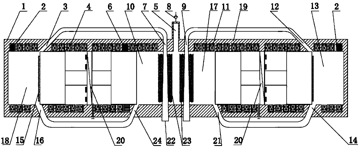
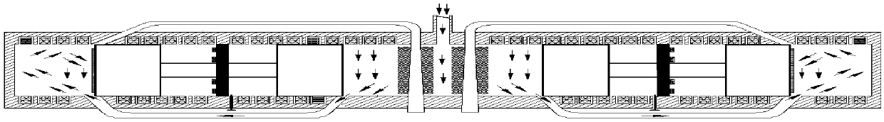
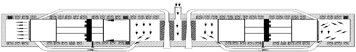
[0031] Such as figure 1 As shown, a HCCI micro-free piston generator includes a stator and a miniature free-piston power plant. The stator is provided with a main air inlet 5, and the stator is divided into left and right parts with symmetrical distribution and the same structure through the main air inlet 5. The stator working unit 1 and the right stator working unit 19; the left stator working unit 1 is provided with a fixed split ring 20; the miniature free piston power unit is a single magnetic piston structure, and the left stator working unit 1 is provided with The miniature free piston power unit, and the piston rod of the miniature free piston power unit passes through the split ring 20, and the miniature free piston power unit slides in the left stator working un...


PUM


Abstract

The invention provides an HCCI micro free piston electric generator. The HCCI micro free piston electric generator comprises a stator and micro free piston power devices. The stator is provided with amain air inlet, the stator is divided into stator work units through the main air inlet, the stator work units are symmetrically distributed and are of the same structure, fixed dividing rings are arranged in the stator work units, the micro free piston power devices are arranged in the stator work units, a work chamber comprises a combustion chamber and a pressure chamber, the pressure chamber is communicated with the main air inlet, a combustion chamber air inlet and a combustion chamber exhaust opening are formed in the combustion chamber, a pressure chamber air inlet is formed in the pressure chamber, the pressure chamber air inlet and the combustion chamber air inlet are connected through a pipeline, a one-way valve is arranged on the main air inlet, and an exciting winding and a stator winding are arranged on the inner wall of each stator work unit. Mechanical energy is directly converted into electric energy, waste gas waste heat is used for preheating mixed gas, the initial temperature of the mixed gas is improved, and compression combustion of the mixed gas is facilitated.

Description

technical field [0001] The invention relates to a micro power system related to the field of internal combustion engines and the field of power generation, in particular to an HCCI micro free piston generator. Background technique [0002] As a new type of power device, micro electromechanical power system is widely used in various fields of people's life, and has a good development prospect. Compared with general power sources, such as lithium batteries, power devices using hydrocarbon fuels have the advantages of low energy density, low emissions, and low pollution, which makes the miniaturization and portability of equipment possible. The mechanical structure of the micro-free piston power unit does not have the crank connecting rod, gas valve and other mechanisms of the traditional internal combustion engine. The free piston moves in a straight line in the cylinder without being constrained by mechanical force, but there is a large heat transfer loss caused by a relative...

Claims


Application Information

Patent Timeline
Patent Type & Authority Applications(China)
IPC IPC(8): F02B71/04F02F3/12F02M27/02F02M31/08F01N5/02
CPCF01N5/02F02B71/04F02F3/12F02M27/02F02M31/08Y02T10/12
Inventor 赵岩王谦黄蓉禹莉莉
Owner 泰州市海创新能源研究院有限公司
Why Eureka
Try Eureka