An integrated forming method for parts with multi-material gradient lattice structure

A lattice structure, multi-material technology, applied in the direction of additive processing, process efficiency improvement, transportation and packaging, etc., can solve the difficulty of forming lattice structure of aluminum matrix composite materials, difficult to control the bonding of interfaces, and the absorption of laser light by aluminum. Low problems, to achieve the effect of solving interface mismatch, high processing flexibility, and good interface bonding

Active Publication Date: 2020-01-21
HUAZHONG UNIV OF SCI & TECH
View PDF5 Cites 0 Cited by
  • Summary
  • Abstract
  • Description
  • Claims
  • Application Information

AI Technical Summary

Problems solved by technology

Although SLM has a very high energy density, the absorption of aluminum to laser light is very low, for example, the absorption rate of laser light with a wavelength of 1um is about 7%, and it is very easy to oxidize during processing, and the bonding of the interface between composite materials is also difficult to control , which brings difficulties to the formation of lattice structures of aluminum matrix composites

Method used


Image

  • An integrated forming method for parts with multi-material gradient lattice structure

Examples


Embodiment 1

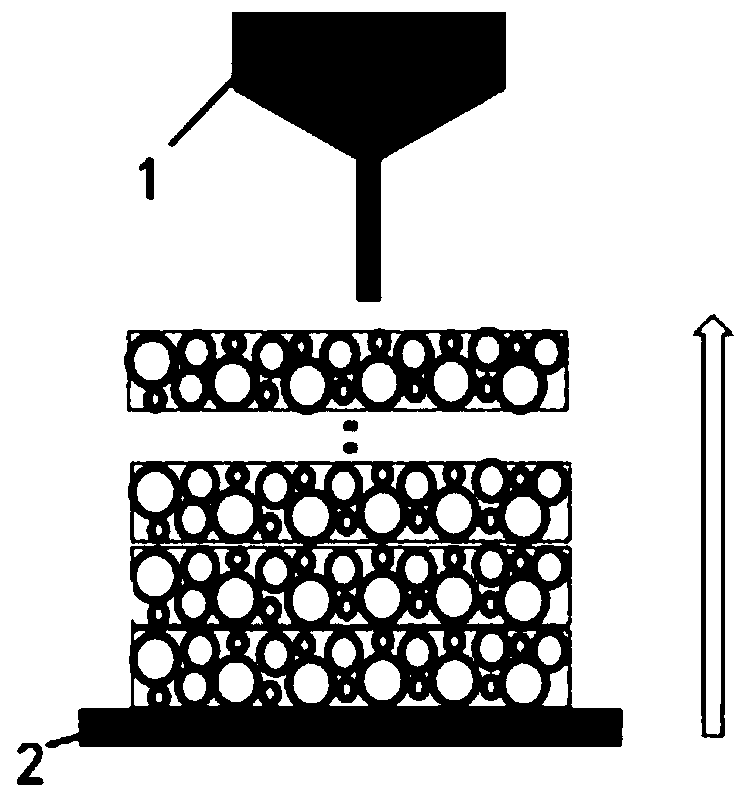
[0028] (1) Select AlSi10Mg powder with a particle size of 15-50um and a spherical SiC powder with an average particle size of 40nm prepared by the gas atomization method, and carry out low-speed processing according to the mass ratio of 99:1, 98:2, and 97:3, respectively. Three parts of aluminum-based composite powder 1 were obtained by ball milling, wherein the ball milling speed was 150 rpm and the time was 1.5 h.

[0029] (2) Fix and preheat the aluminum substrate 2 to 150° C., and pump the oxygen content in the forming cavity to below 0.01%.

[0030] (3) Slice the 3D CAD model of the optimized gradient lattice to obtain the corresponding STL format file, input it into the computer, and the SLM equipment is controlled by the computer under the protective atmosphere, and the powder dropping cylinder drops a certain layer thickness according to the processing layer thickness each time The powder is finished with a powder spreading stick, the laser source is a 400W fiber laser...

Embodiment 2

[0033] (1) Select AlSi10Mg powder with a particle size of 15-50um normally distributed and spherical Al2O3 powder with an average particle size of 30nm prepared by the gas atomization method, and perform low-speed ball milling according to the mass ratio of 99:1, 98:2, and 97:3 , to obtain three parts of aluminum-based composite powder 1, wherein the ball milling speed is 100 rpm and the time is 2 h.

[0034] (2) Fix and preheat the aluminum substrate 2 to 200°C, and pump the oxygen content in the forming cavity to below 0.01%.

[0035](3) Slice the 3D CAD model of the optimized gradient lattice to obtain the corresponding STL format file, input it into the computer, and the SLM equipment is controlled by the computer under the protective atmosphere, and the powder dropping cylinder drops a certain layer thickness according to the processing layer thickness each time The powder is finished with a powder spreading stick, the laser source is a 400W fiber laser, the power is set ...

Embodiment 3

[0038] (1) Select AlSi10Mg powder with a particle size of 15-50um normally distributed and spherical TiB2 powder with an average particle size of 50nm prepared by the gas atomization method, and perform low-speed ball milling according to mass ratios of 99:1, 98:2, and 97:3 , to obtain three parts of aluminum-based composite powder 1, wherein the ball milling speed is 200 rpm and the time is 1 h.

[0039] (2) Fix and preheat the aluminum substrate 2 to 100°C, and pump the oxygen content in the forming cavity to below 0.01%.

[0040] (3) Slice the 3D CAD model of the optimized gradient lattice to obtain the corresponding STL format file, input it into the computer, and the SLM equipment is controlled by the computer under the protective atmosphere, and the powder dropping cylinder drops a certain layer thickness according to the processing layer thickness each time The powder is finished with a powder spreading stick, the laser source is a 400W fiber laser, the power is set at ...


PUM

PropertyMeasurementUnit
particle sizeaaaaaaaaaa

Abstract

The invention belongs to the field of rapid manufacturing, and discloses an integrated forming method for parts with a multi-material gradient lattice structure, comprising the following steps: (1) preparing an aluminum-based composite powder suitable for SLM forming: combining aluminum alloy powder with a reinforcement The particles are mixed in various mass ratios and then ball milled for each part of the aluminum-based composite powder; (2) Fix the aluminum substrate on the forming table of the SLM equipment to preheat the aluminum substrate; (3) Replace the molded parts with different components The aluminum-based composite powder is used to form the upper layer, thereby manufacturing a multi-material gradient lattice structure part with continuously changing structure and composition; (4) cooling the part and performing wire cutting to obtain a gradient lattice structure part. The aluminum-based composite powder of the present invention has uniform distribution and good interfacial bonding, which solves the problem of interface mismatch between metal and ceramics, and eliminates sudden changes in the interface, eliminating the sudden change in physical properties caused by the sudden change of interface, reducing the thermal stress.

Description

technical field [0001] The invention belongs to the field of rapid manufacturing, and more specifically relates to an integrated forming method for parts with a multi-material gradient lattice structure. Background technique [0002] With the advancement of mechanical fields such as aerospace, ships, and automobiles, materials have become a key factor restricting their development, especially for high-performance components serving in harsh environments, which have stricter requirements on structure and performance. Taking the insulation layer of the cabin of a high-speed aircraft as an example, as the flight speed increases, its aerodynamic heating environment becomes more and more severe. When the flight speed increases from 5 Mach (Ma) to 7 Ma, the surface temperature of the large area of ​​the substrate increases from 650 ° C to 1800 ° C; when the speed increases to 10 Ma, the external temperature can increase to 2200 ° C, however, the temperature in the cabin must not b...

Claims


Application Information

Patent Timeline
Patent Type & Authority Patents(China)
IPC IPC(8): B22F3/105B22F1/02B33Y10/00B33Y70/00
CPCB33Y10/00B33Y70/00B22F10/00B22F1/052B22F1/16B22F10/36B22F10/68B22F10/66B22F10/366B22F10/34B22F12/17B22F10/28B22F10/32Y02P10/25
Inventor 宋波王敏史玉升
Owner HUAZHONG UNIV OF SCI & TECH
Why Eureka
Try Eureka