Method for high-yield low carbon olefin and system for high-yield low carbon olefin
A low-carbon olefin and reactor technology, which is applied in the treatment of hydrocarbon oil, hydrocarbon oil treatment products, petroleum industry, etc., can solve the problem of limited increase in propylene yield, and achieve the effect of extending the operation period
- Summary
- Abstract
- Description
- Claims
- Application Information
AI Technical Summary
Problems solved by technology
Method used
Image
Examples
Embodiment 1
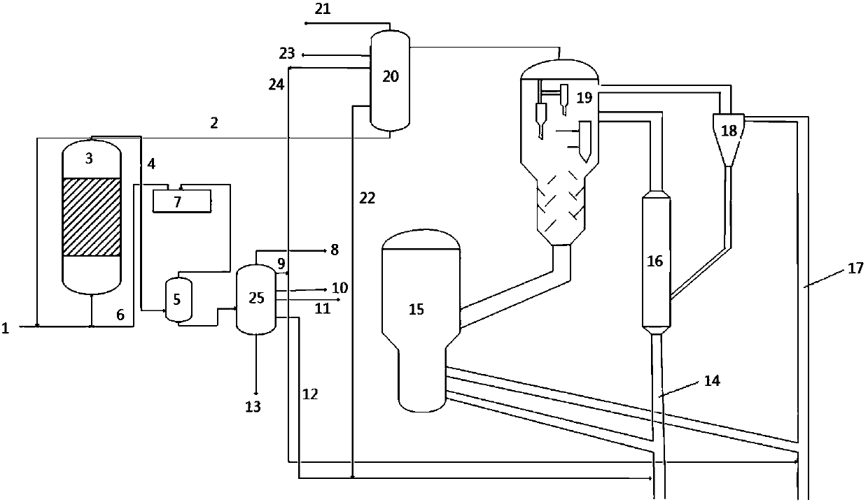
[0105] This embodiment adopts figure 1 The process flow diagram shown is carried out, specifically:
[0106] Introducing the residual oil raw material with properties shown in Table 1 into an ebullating bed hydrocracking reaction zone for hydrocracking reaction to obtain hydrocracking reaction effluent;
[0107] The hydrocracking reaction effluent is separated, and the hydrogen-rich gas in the gas phase product at the top of the separated high-pressure separator is processed by a circulating hydrogen compressor to obtain circulating hydrogen, and the circulating hydrogen is used to circulate back to the ebullated bed for hydrogenation In the cracking reaction zone, the separated liquid-phase product is introduced into the fractionating tower for fractionation to obtain the first dry gas and the first liquefied gas (note: the content of low-carbon olefins in the first liquefied gas is very small, therefore, in the embodiment The yield of low-carbon olefins in the results does ...
Embodiment 2-3
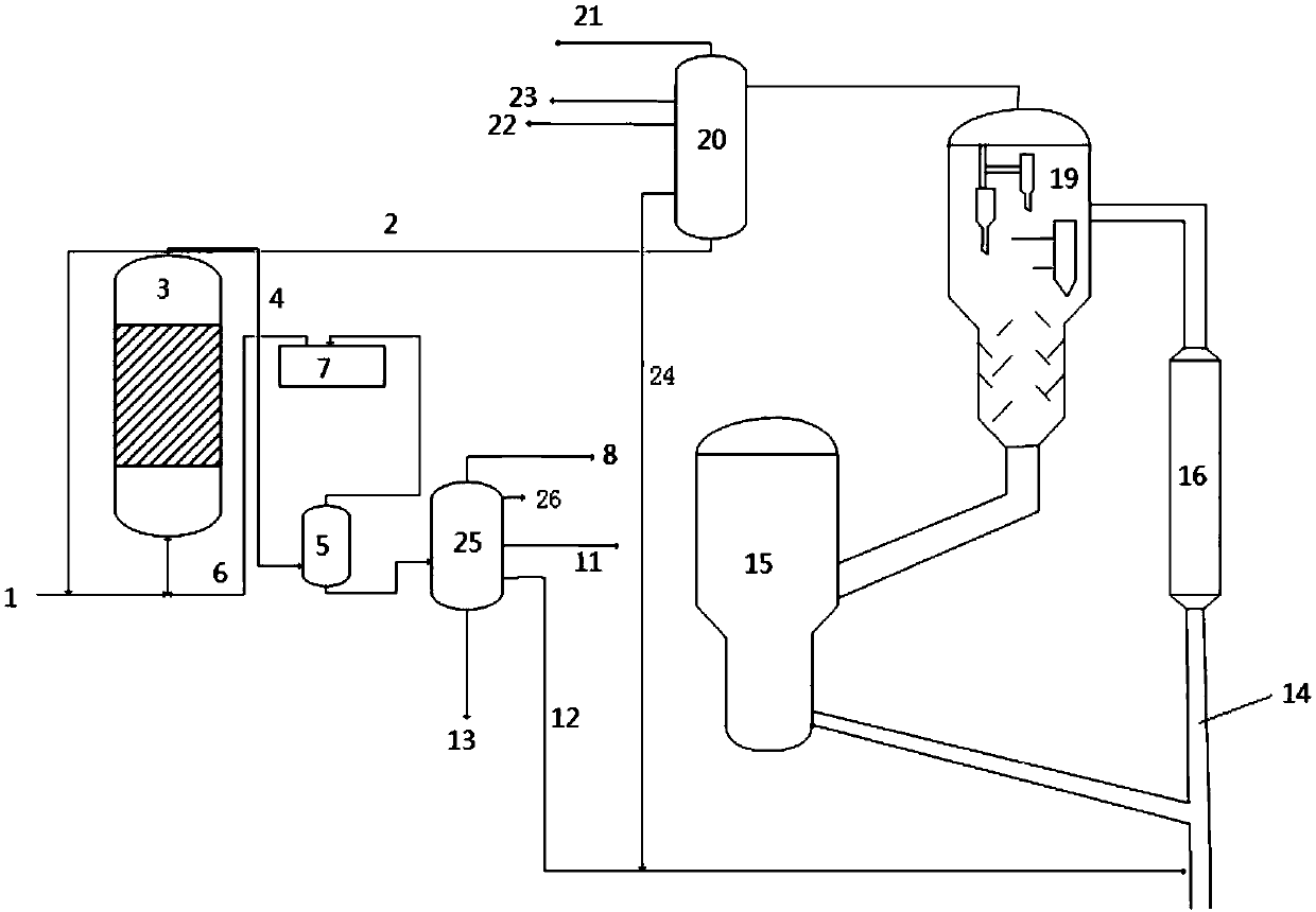
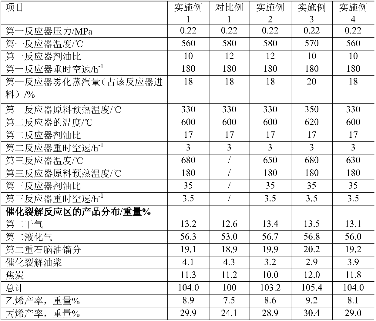
[0123] Embodiment 2-3 is carried out using the same process flow as Example 1. The difference is that the reaction conditions and product distribution in the ebullated bed hydrocracking reaction zone of Embodiment 2-3 are as shown in Table 3, and the catalytic cracking The reaction conditions in the reaction zone are shown in Table 4. The product distribution obtained by the method of Examples 2-3 is shown in Table 4.
Embodiment 4
[0125] The present embodiment adopts the method similar to embodiment 1 to carry out, and difference is that the reaction temperature in the third reactor of the catalytic cracking reaction zone of the present embodiment is 30 ℃ higher than the reaction temperature in the second reactor, specifically , The reaction conditions and product distribution of the ebullating bed hydrocracking reaction zone of this embodiment are shown in Table 3, and the reaction conditions of the catalytic cracking reaction zone are shown in Table 4. The product distribution obtained by the method of this embodiment is shown in Table 4.
[0126] From the above results of the present invention, it can be seen that the method of the present invention organically combines the fluidized bed residual oil hydrogenation process with the catalytic cracking process according to the properties and characteristics of the fluidized bed residual oil hydrocracking product, which can significantly improve the propy...
PUM
| Property | Measurement | Unit |
|---|---|---|
| density | aaaaa | aaaaa |
| diameter | aaaaa | aaaaa |
| specific surface area | aaaaa | aaaaa |
Abstract
Description
Claims
Application Information
 - R&D
- Intellectual Property
- Life Sciences
- Materials
- Tech Scout
- Unparalleled Data Quality
- Higher Quality Content
- 60% Fewer Hallucinations
Browse by: Latest US Patents, China's latest patents, Technical Efficacy Thesaurus, Application Domain, Technology Topic, Popular Technical Reports.
© 2025 PatSnap. All rights reserved.Legal|Privacy policy|Modern Slavery Act Transparency Statement|Sitemap|About US| Contact US: help@patsnap.com


