Broadband confocal method and device to measure refractive index of infrared lens element

A technology of measuring device and measuring method, which is applied in the field of measuring the refractive index of broadband confocal infrared lens elements, can solve the problems of complex measurement process, low precision, and inability to directly measure the refractive index of lens elements, and achieve high measurement accuracy and focused beam No dispersion, the effect of improving the measurement range and accuracy of the optical path

Active Publication Date: 2018-03-09
BEIJING INSTITUTE OF TECHNOLOGYGY
View PDF8 Cites 8 Cited by
  • Summary
  • Abstract
  • Description
  • Claims
  • Application Information

AI Technical Summary

Problems solved by technology

[0013] The purpose of the present invention is to overcome the defects that the existing refractive index measurement technology cannot directly measure the refractive index of the lens element, the measurement process is complicated, and the precision is low, and propose a wide-band differential confocal infrared lens element refractive index measurement method and device, in order to realize High-precision non-contact measurement of the refractive index of lens elements at any wavelength in the visible and infrared broadband range

Method used


Image

  • Broadband confocal method and device to measure refractive index of infrared lens element
  • Broadband confocal method and device to measure refractive index of infrared lens element
  • Broadband confocal method and device to measure refractive index of infrared lens element

Examples


Embodiment 1

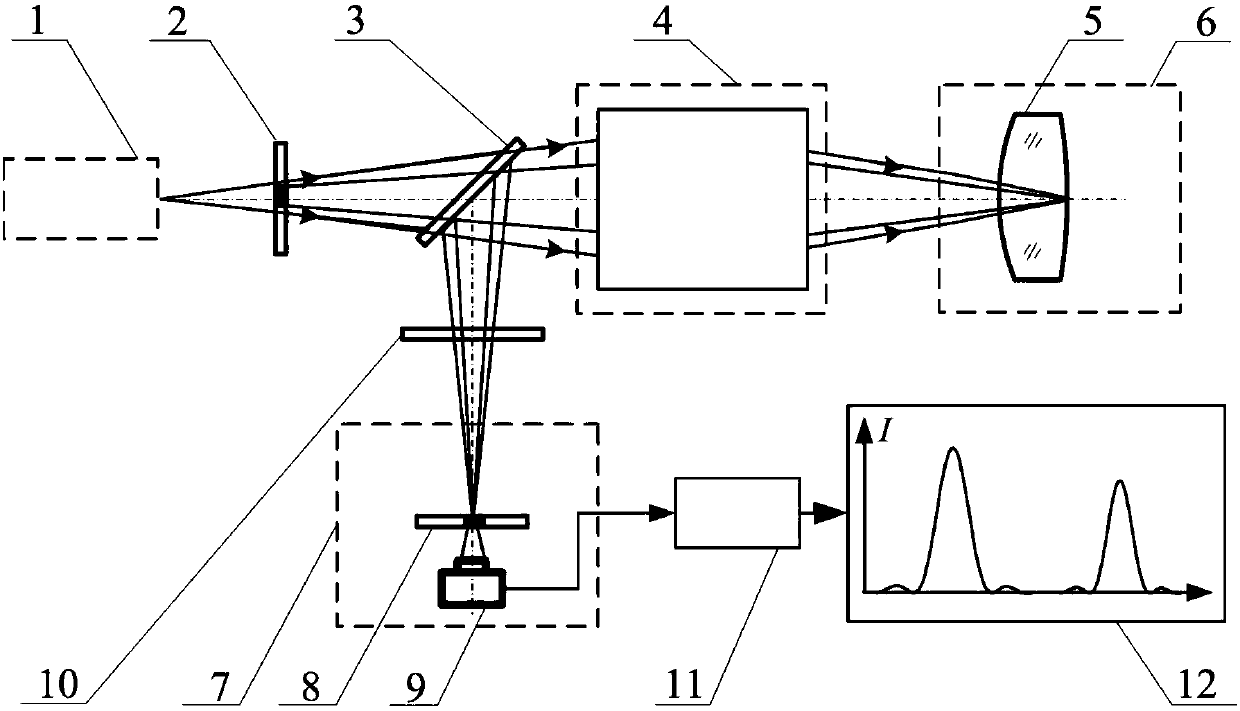
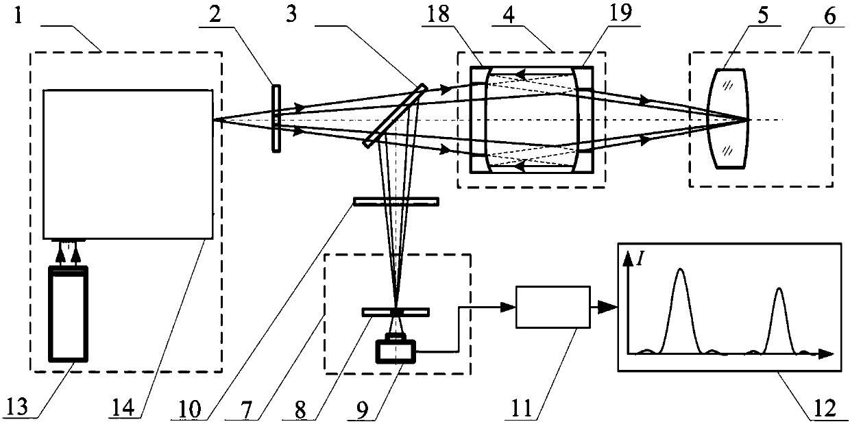
[0048] The embodiment of the present invention is based on Figure 4 The wide-band confocal infrared lens element refractive index measurement device shown is composed of a silicon carbon black body light source 13 and a grating monochromator 14 figure 1 Broadband point source system in 1. Composed of attitude adjustment system 20 and axial drive system 21 figure 1 In the adjustment and driving system 6, the wide-band spectroscopic system 3 adopts a wide-band spectroscopic sheet, and the detector 9 adopts a photodetector.

[0049] like Figure 4 As shown, the wide-band confocal infrared lens element refractive index measurement device includes: a silicon carbon black body light source 13, a grating monochromator 14 located in the exit direction of the silicon carbon black body light source 13, and a pupil filter located in the exit direction of the grating monochromator 14 2, wide-band spectroscopic system 3, wide-band collimation and convergence system 4, adjustment and dr...

Embodiment 2

[0066] like Figure 5 In the shown broadband confocal infrared lens element refractive index measurement device, the device is composed of a silicon carbon black body light source 13 and a filter group monochromator 14 figure 1 The wide-band point light source system 1 is composed of a five-dimensional adjustment frame as the attitude adjustment system 20 and an air bearing guide rail as the axial drive system 21 figure 1 Adjustment and drive system in 6.

[0067] All the other measuring methods are the same as in Example 1.


PUM


Abstract

The invention relates to a broadband confocal method and device to measure refractive index of an infrared lens element and belongs to the technical field of optical precision measurement. A black light source is used herein to generate a lighting point source of specific wavelength through a wavelength gating system, a confocal light path is used to perform chromatographic focus fixation on apexes of front and rear surfaces of a lens under measurement, optical thickness of the lens under measurement is acquired by measuring, element refractive index of the lens is acquired by calculating through a ray tracking algorithm, and high-precision noncontact measurement of element refractive index of an infrared lens under any wavelength in a wide band range of from visible light to infrared is achieved. The method and device of the invention have the advantages that destructive sampling on a lens under measurement is not required, nondestructive direct measurement of element refractive indexof the lens under any wavelength from visible light to infrared is achieved, the measuring process is convenient, measurement precision is high, the ability to resist ambient interferences is great,and a brand-new effective technical means to detect the element refractive index of the lens is provided.

Description

technical field [0001] The invention belongs to the technical field of optical precision measurement, which combines the technology of point light source generation at any wavelength in the visible to infrared wide band, confocal tomography fixed focus technology and ray tracing refractive index calculation algorithm, and relates to a wide band confocal infrared lens element refraction The method and device for measuring the refractive index can be used for high-precision direct measurement of the refractive index of a lens element under the condition of any wavelength in the visible to infrared band. technical background [0002] Refractive index measurement is widely used in the fields of optical processing, precision inspection and test metrology. Although the traditional measurement techniques such as minimum deviation angle method, prism coupling method and Abbe method are relatively mature, the accuracy can reach 10 -6 order of magnitude, but the measured material need...

Claims


Application Information

Patent Timeline
Patent Type & Authority Applications(China)
IPC IPC(8): G01N21/41G01N21/01
CPCG01N21/01G01N21/4133
Inventor 邱丽荣王允赵维谦
Owner BEIJING INSTITUTE OF TECHNOLOGYGY
Why Eureka
Try Eureka