Field failure-considered robust fault-tolerant prediction control method and device

A predictive control and fault technology, applied in the field of permanent magnet synchronous motor control equipment, can solve the problems of control system divergence, model parameter mismatch, limited current predictive control application, etc.

Active Publication Date: 2018-03-09
HUNAN UNIV OF TECH
View PDF2 Cites 16 Cited by
  • Summary
  • Abstract
  • Description
  • Claims
  • Application Information

AI Technical Summary

Problems solved by technology

However, since the permanent magnet synchronous motor is a time-varying control object, in actual operation, the parameters of the motor often change due to material degradation or different operating conditions
This will lead to perturbation of resistance and inductance parameters and demagnetization of permanent magnets
The perturbation of resistance and inductance parameters and the demagnetization of permanent magnets will cause model parameter mismatch, which will affect the performance of the control system and even cause the control system to diverge.
In addition, the delay problem of the digital control system will also affect the performance of the control system
The existence of the above problems seriously limits the application of current predictive control in actual industry.
[0004] At present, there is no current control method that can simultaneously solve the influence of resistance, inductance parameter perturbation, permanent magnet demagnetization and current one-beat delay.

Method used


Image

  • Field failure-considered robust fault-tolerant prediction control method and device
  • Field failure-considered robust fault-tolerant prediction control method and device
  • Field failure-considered robust fault-tolerant prediction control method and device

Examples


Embodiment

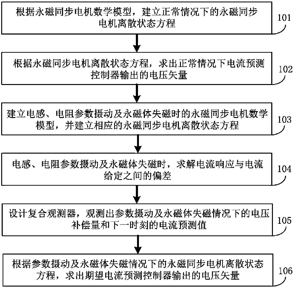
[0071] figure 1 It is a flowchart of an embodiment of the robust fault-tolerant predictive control method considering the loss of field fault provided by the present invention. The robust fault-tolerant predictive control method includes the following steps:

[0072] Step 101, according to the mathematical model of the permanent magnet synchronous motor, establish the discrete state equation of the permanent magnet synchronous motor under normal conditions,

[0073] i(k+1)=E o (k)·i(k)+F o ·u(k)+P o (k)

[0074] In the formula, i(k)=[i d (k)i q (k)] T , u(k)=[u d (k) u q (k)] T , u d (k), u q (k), i d (k), i q (k) are the voltage and current on the d and q axes respectively; ω(k) is the electrical angular velocity; ψ ro , R, L d , L q are permanent magnet flux linkage, stator resistance and d, q axis inductance respectively; T s is the sampling period.

[0075] Step 102, according to the discrete state equation of the permanent magnet synchronous motor, o...


PUM


Abstract

The invention discloses a field failure-considered robust fault-tolerant prediction control method and a device. The method comprises the following steps of firstly, designing a composite observer, wherein a voltage compensation amount and a current prediction value at the next moment are observed at the same time by the observer according to a motor stator current, a stator voltage and a motor rotating speed in two-phase rotating coordinate system; secondly, obtaining a robust fault-tolerant prediction control method through responding to a quick and accurate tracking command current based onthe non-differential-beat control principle. According to the method, the influence of system parameter perturbation and permanent magnet demagnetization on current vectors is eliminated through adding the voltage compensation amount. The sampling current value at the current moment is replaced by the current prediction value at the next moment, so that the one-beat delay compensation of the current can be realized. Finally, the space vector pulse width SVPWM modulation is carried out on an obtained new voltage command, so that a six-path PWM pulse signal for driving a motor to run is obtained. According to the invention, the current fast non-static tracking under the condition of motor parameter perturbation and permanent magnet demagnetization is realized. The harmonic current is reduced, and the control performance of a current loop is optimized. The method and the device can be widely applied to occasions wherein a permanent magnet synchronous motor is adopted as a driving system.

Description

technical field [0001] The invention belongs to the technical field of permanent magnet synchronous motor control equipment, and in particular relates to a robust fault-tolerant predictive control method and device considering demagnetization faults. Background technique [0002] The permanent magnet synchronous motor is a nonlinear, strongly coupled multivariable control object, and the direct relationship between the current and the electromagnetic torque can be obtained by using the vector control method. The quick response of electromagnetic torque and low torque ripple are one of the important indicators to measure the performance of servo system. Therefore, the dynamic characteristics of the current loop, which is directly related to the electromagnetic torque, has become the core factor to determine the dynamic quality of the servo system. The high-performance permanent magnet synchronous motor servo control system requires a fast-response current inner loop, which r...

Claims


Application Information

Patent Timeline
Patent Type & Authority Applications(China)
IPC IPC(8): H02P21/22H02P21/13H02P25/022
CPCH02P21/13H02P2207/05H02P21/22H02P25/024
Inventor 张昌凡吴公平黄守道何静冯江华刘建华林真珍
Owner HUNAN UNIV OF TECH
Why Eureka
Try Eureka