
Catalytic oxidation deodorization process and catalytic oxidation deodorization device

A catalytic oxidation and process technology, applied in chemical instruments and methods, gas treatment, membrane technology, etc., can solve the problems of ozone overflow, surrounding environment damage, etc., and achieve the effects of sufficient reaction contact area, low energy consumption, and high processing efficiency

Inactive Publication Date: 2018-03-13
深圳市利源水务设计咨询有限公司
View PDF8 Cites 0 Cited by
  • Summary
  • Abstract
  • Description
  • Claims
  • Application Information

AI Technical Summary

Problems solved by technology

However, if the dosage is not well controlled, a certain amount of ozone will overflow in the exhaust gas, which is another kind of damage to the surrounding environment.

Method used


Image

  • Catalytic oxidation deodorization process and catalytic oxidation deodorization device
  • Catalytic oxidation deodorization process and catalytic oxidation deodorization device
  • Catalytic oxidation deodorization process and catalytic oxidation deodorization device

Examples


Embodiment 1

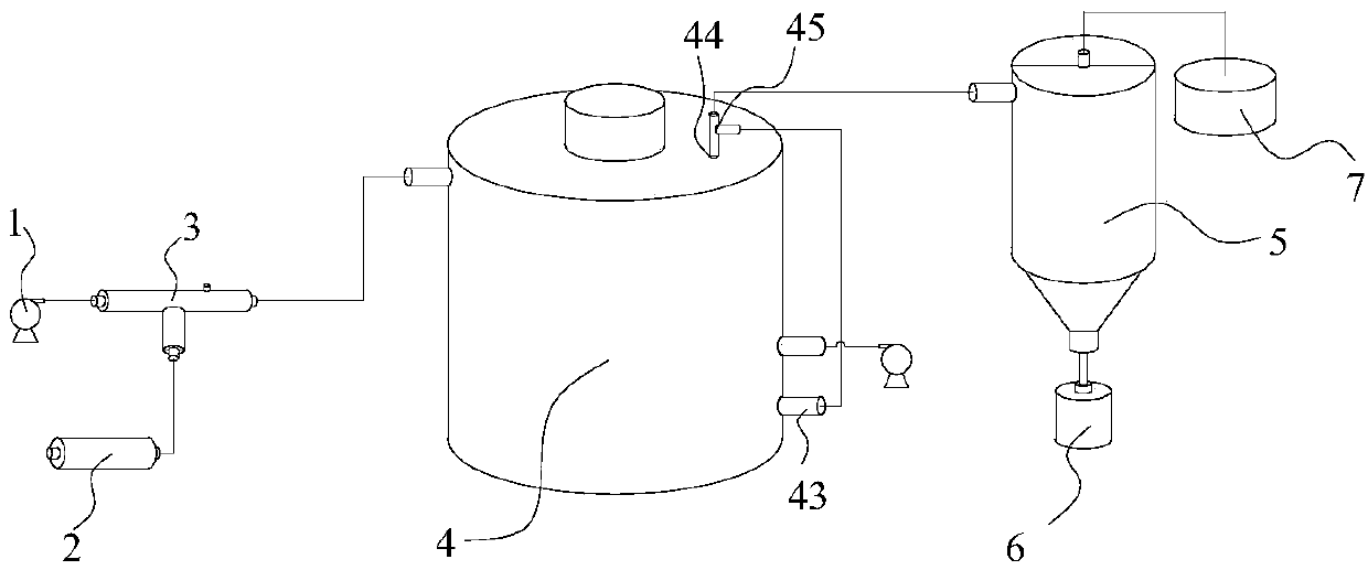
[0043] A catalytic oxidation deodorization process, comprising the following steps:

[0044] 1) Ozone is produced by an ozone generator, and ozone is mixed with high-pressure water through a jet mixer; the pressure of the high-pressure water is 3kg / cm 2 ;

[0045] 2) Using hematite slag as a catalyst, the jet mixed gas-liquid obtained in step 1) is used to treat the odor at a pH of 3-4 and a temperature of 30°C;

[0046]3) Carry out gas-liquid separation to the odor after step 2) treatment.

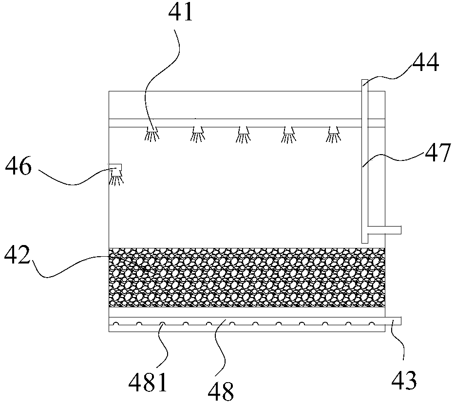
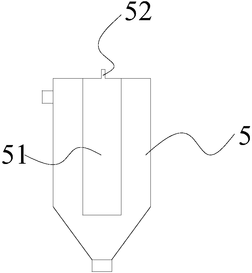
[0047] Implement the catalytic oxidation deodorization device of this method, comprise high-pressure injection head 1, ozone generator 2, jet mixer 3, oxidation reaction tower 4 and gas-liquid separator 5; Described oxidation reaction tower is provided with filler 42, and filler is red Iron ore slag, the particle diameter of filler is 20-30mm, the height of described oxidation reaction tower is 3m, and the height of filler is 1.8m; The top of described oxidation reaction tower is provid...

Embodiment 2

[0054] On the basis of embodiment 1, embodiment 2 also increases automatic control system, comprises control system, ozone concentration detector, pH detector and odor detector, and described ozone concentration detector is used for detecting the concentration signal of ozone in the reaction system And feed back to the control system, the control system adjusts the flow of the ozone generator according to the concentration signal instruction of the ozone; the pH detector is used to detect the pH value signal in the oxidation reaction tower and feeds back to the control system, The control system adjusts the opening or closing of the acid liquid nozzle according to the pH value signal instruction; the odor detector is used to detect H 2 S and / or NH 3 The concentration signal and feed back to the control system, the control system according to the H 2 S and / or NH 3 The concentration signal instructs the discharge port to discharge or not.


PUM

PropertyMeasurementUnit
Particle sizeaaaaaaaaaa
Heightaaaaaaaaaa

Abstract

The invention discloses a catalytic oxidation deodorization process. The process comprises the following steps: (1) mixing ozone with high pressure water by using a jet mixer, wherein the pressure ofthe high pressure water is 2.5-4kg / cm<2>; (2) treating the odor of jetted mixed liquid, obtained in the step (1), by taking hematite slag as a catalyst under the conditions that the pH value is 3-5 and the temperature is 15-25 DEG C; (3) carrying out gas-liquid separation on the odor treated in the step (2). The catalytic oxidation deodorization device comprises a high pressure injector head, an ozonator, the jet mixer, an oxidation reaction tower and a gas-liquid separator, wherein the oxidation reaction tower is internally filled with the hematite slag. According to the process and the device, the ozone is mixed with the high pressure water, so that gaseous ozone molecules and liquid water are fully mixed with each other, are activated, and collide with each other; therefore, the reaction contact area is enlarged, and deodorization is more efficient.

Description

technical field [0001] The invention relates to the field of sewage treatment, in particular to a catalytic oxidation deodorization process and a device thereof. Background technique [0002] The odor produced by facilities such as sewage treatment plants, drainage pumping stations and regional garbage collection and delivery stations in municipal engineering will have a certain impact on the surrounding living environment. The main malodorous component of this type of odor is H 2 S and ammonia and other gases with certain reducing properties. This type of gas adopts the method of physical adsorption, [0003] As the country strengthens the protection of the environment, various deodorization technologies have been developed rapidly in recent years, such as acid and alkali absorption, biological oxidation, physical adsorption and chemical oxidation, etc. have been applied in deodorization processes. For acid and alkali or physical adsorption, the loading capacity of the a...

Claims


Application Information

Patent Timeline
IPC IPC(8): B01D53/86B01D53/58B01D53/52
CPCB01D53/8612B01D53/8634B01D2251/106B01D2257/90
Inventor 钟颖孙艳丽曲祥瑞臧翀刘起香
Owner 深圳市利源水务设计咨询有限公司
Learn More