
Microwave calorimeter for measuring material microwave heat effect and its calorimetric method

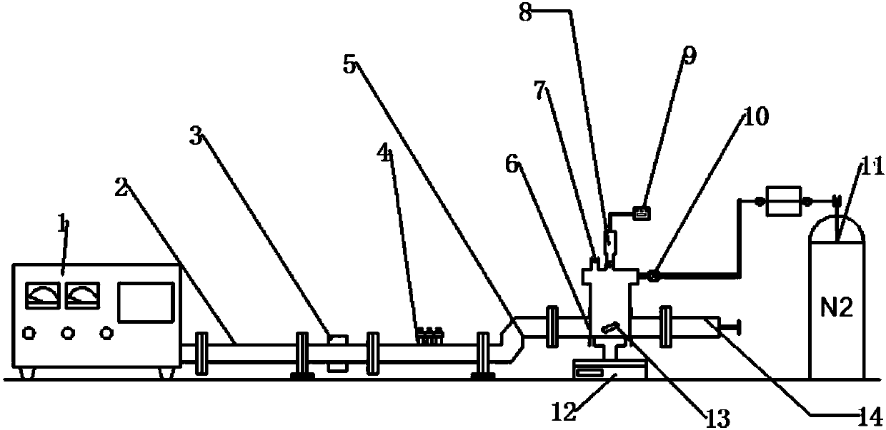
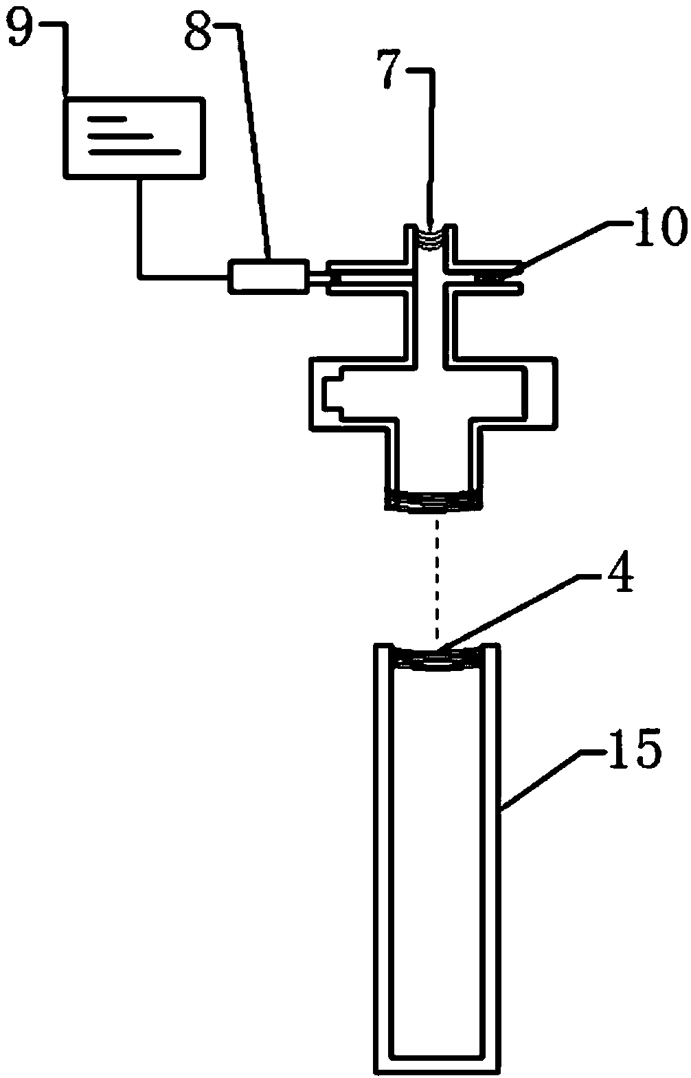
A technology of thermal effect and calorimeter, which is applied in the direction of material analysis, measuring device, and material analysis using microwave means, which can solve the problems of restricting the microwave absorption ability of materials, affecting the accuracy of results, and difficult control of pressure and power, so as to avoid Hot spot effect, avoid weighing process, high sensitivity effect

Active Publication Date: 2018-03-13
SHANDONG UNIV
View PDF2 Cites 7 Cited by
  • Summary
  • Abstract
  • Description
  • Claims
  • Application Information

AI Technical Summary

Problems solved by technology

However, the traditional microwave calorimeter needs to be improved in the use of this temperature measurement method. It is necessary to use a thermometer to measure the temperature after the microwave stops. This process will cause a lot of heat loss and affect the accuracy of the results.
In addition, the traditional calorimetry method is relatively cumbersome in terms of process, requiring a series of processes such as weighing, parameter adjustment, reaction, and temperature measurement, which cannot be continuously measured
In addition, some operating parameters such as pressure and power are difficult to control, which restricts the research on the influence of these parameters on the absorbing ability of materials.

Method used


Image

  • Microwave calorimeter for measuring material microwave heat effect and its calorimetric method
  • Microwave calorimeter for measuring material microwave heat effect and its calorimetric method
  • Microwave calorimeter for measuring material microwave heat effect and its calorimetric method

Examples


Embodiment 2

[0047] The above-mentioned microwave calorimeter is used for measurement, carbon felt is used as the target material, and paraffin oil is used as the intermediate medium. Take 0.1g of carbon felt and 15g of paraffin oil into the reaction chamber through the liquid injection port 7, seal the reaction vessel, select 0s, 10s, 20s, 30s, 40s, 50s, and 60s as time parameters, and pass the pressure sensor 8 It is converted into a digital signal and displayed on the display panel 9 to obtain the temperature values ​​at these 7 moments. The room temperature was 22°C during the measurement, and the temperature values ​​at seven moments were 22°C, 46.4°C, 80.9°C, 101.2°C, 116.1°C, 140.5°C, and 156.2°C. From the above experimental results, it can be seen that the carbon felt can be irradiated with microwaves for one minute. The temperature rise of the intermediate medium reaches nearly 150°C, and this device accurately and clearly characterizes the microwave thermal effect of carbon felt....


PUM


Abstract

The invention discloses a microwave calorimeter for measuring material microwave heat effect and its calorimetric method. The microwave calorimeter comprises a measurement control device and a microwave generating device, a reaction cavity body and an air pressure adjusting device which are connected to the measurement control device; the joint of the reaction cavity and the other parts is furtherprovided with a sealing device, and an isolating device is connected to the middle of the microwave generating device and the reaction cavity; a guide wave device for placing the microwave reflectionis arranged in the isolating device, the microwave generated by the microwave generating device enters the reaction cavity body through the isolating device; the reaction cavity body is connected with an air pressure adjusting device. After absorbing the microwave energy by means of internal loss medium, temperature is risen up to make the change of pressure intensity in the cavity, and the measurement of the medium temperature is further realized. Through pressure change, the microwave calorimetric effect under different working condition parameters is measured; the wave absorbing ability ofthe material is presented; the microwave calorimeter has the advantages of big range, high sensitivity, and others.

Description

technical field [0001] The invention relates to microwave thermal effect technology, in particular to a microwave calorimeter and a calorimetric method for measuring the microwave thermal effect of materials. Background technique [0002] In recent years, microwave technology has been developed with each passing day. Among them, the research and application of microwave heating in food processing, drying, sintering, welding, metallurgy, plasma processing, solution sol processing, polymer material processing, functional material preparation, organic solid waste pyrolysis, pollutant control, etc. been continuously expanded. What is closely related to the utilization of microwaves is microwave absorbing materials. Microwave absorbing materials, also known as microwave absorbing materials, refer to a type of material that effectively absorbs incident microwaves, converts microwaves into heat energy and consumes them, or makes microwaves interfere and cancel each other. At pre...

Claims


Application Information

Patent Timeline
IPC IPC(8): G01N22/00
CPCG01N22/00
Inventor 毛岩鹏薛超
Owner SHANDONG UNIV
Learn More