
Molecular distillation device

A technology of molecular distillation and equipment, which is applied in the field of molecular distillation equipment, can solve the problems of short time, generally only ten seconds to a few minutes, complicated manufacturing and maintenance, and high manufacturing requirements.

Pending Publication Date: 2018-03-27
饶攀
View PDF2 Cites 0 Cited by
  • Summary
  • Abstract
  • Description
  • Claims
  • Application Information

AI Technical Summary

Problems solved by technology

2. Ordinary distillation has bubbling and boiling phenomena, while molecular distillation is free evaporation on the surface of the liquid film, and the operating pressure is very low. Generally, it is on the order of 0.1-1Pa, and the heating time is very short, generally only ten seconds to several minutes.
3. Evaporation and condensation in ordinary distillation are reversible processes, and there is a dynamic phase equilibrium between the liquid phase and the gas phase, while in the molecular distillation process, the molecules escaping from the heating surface fly directly to the condensation surface, and theoretically do not return to the heating surface Possibility, so molecular distillation has no hard-to-separate substances
[0003] The applicant’s associated patent applied for an invention patent on August 7, 2012. The invention patent number is ZL201210277674.7. The molecular distillation equipment includes a molecular distillation equipment body and a vacuum tube. The molecular distillation equipment body is an upper ring larger than a lower ring. The inverted body of the ring is an annular round platform, and the material distributor on the top and the molecular distillation equipment of the cooling water pipe have high manufacturing requirements and complicated manufacturing processes. At the same time, in the vacuum chamber, the manufacturing and maintenance are very complicated.

Method used


Image

  • Molecular distillation device
  • Molecular distillation device
  • Molecular distillation device

Examples


Embodiment 1

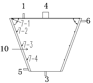
[0037] It includes a molecular distillation equipment body 10 and a vacuum tube 4. The molecular distillation equipment body 10 is an inverted body ring-shaped round platform with an upper ring larger than the lower ring: the two busbars opposite to the inverted body ring-shaped round table are formed by the intersection of the upper bottom The angle is from 10 degrees to 89 degrees; the inner surface of the round platform is the heating surface of the distillation material, and there are several material distributors on the heating surface.

[0038] (1) The two ends of the molecular distillation equipment body 10 are connected to the end caps at both ends, and the top end cap is connected to the material inlet pipe 1. There are multiple material distributors on the heating surface, and the material distributors are processed by steel pipes. circle, the top first material distributor 7-1 has several small holes drilled at the bottom, other material distributors do not need to d...

Embodiment 2

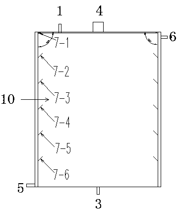
[0045] It includes a molecular distillation equipment body 10 and a vacuum tube 4. The molecular distillation equipment body 10 is an inverted body ring-shaped round platform with an upper ring larger than the lower ring: the two busbars opposite to the inverted body ring-shaped round table are formed by the intersection of the upper bottom The angle is a 90-degree cylinder shape, which is the preferred angle. The cylinder is more convenient to cut and manufacture, and it saves more steel than the circular table shape, and does not cause more waste. The installation takes up less space than the circular table; the cylinder The inner side of the distiller is the heating surface of the distillation material, and there are several material distributors on the heating surface.

[0046] (1) The two ends of the molecular distillation equipment body 10 are connected to the end caps at both ends, and the top end cap is connected to the material inlet pipe 1. There are multiple material...

Embodiment 3

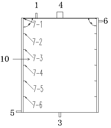
[0052] It includes a molecular distillation equipment body 10 and a vacuum tube 4. The molecular distillation equipment body 10 is an inverted body ring-shaped round platform with an upper ring larger than the lower ring: the two busbars opposite to the inverted body ring-shaped round table are formed by the intersection of the upper bottom The angle is from 10 degrees to 89 degrees; the inner surface of the round platform is the heating surface of the distillation material, and there are several material distributors on the heating surface.

[0053] (1) The two ends of the molecular distillation equipment body 10 are connected to the end caps at both ends, and the top end cap is connected to the material inlet pipe 1. There are multiple material distributors on the heating surface, and the material distributors are processed by steel pipes. circle, the top first material distributor 7-1 has several small holes drilled at the bottom, other material distributors do not need to d...


PUM


Abstract

The invention discloses a molecular distillation device which includes a molecular distillation device body and a vacuum tube. The molecular distillation device body is of a cyclic annular body structure, the top end of the molecular distillation device body is connected with a top seal head, the inner side wall of the molecular distillation device body is a heating face, and the bottom end is provided with a material outlet. The molecular distillation device is characterized in that the angle of an upper corner of the cyclic annular body is 10 DEG to 90 DEG. The molecular distillation devicehas good sealing effect and relatively low cost of device manufacturing and operation maintenance, a stirrer is not needed, a material can form a film automatically along an inclined plane from top tobottom, the continuous production is achieved, the time of the material to pass through the heating surface is short, the quality of the product is good, moreover, an electric power resource is saved, the utilization rate of heat energy is high, and the cost of production is low; if the molecular distillation device can be popularized and applied in related industries, a powerful guarantee can beprovided for improving devices and improving process technologies in related industries.

Description

technical field [0001] The invention belongs to the technical field of mechanical equipment, and relates to equipment for distillation and purification of edible oil products, oleochemical products, other various chemical products, and plant extracts and separation of different components, in particular to molecular distillation equipment. technical background [0002] Molecular distillation, also known as short-path distillation, is a relatively new liquid-liquid separation technology that has not been widely used in industrial production. Its application can solve a large number of problems that cannot be solved by conventional distillation technology. Compared with conventional distillation technology, it has the following advantages: 1. Ordinary distillation operates at the boiling point, while molecular distillation can be separated at any temperature as long as there is a sufficient temperature difference between the hot and cold surfaces. Therefore, the operating temp...

Claims


Application Information

Patent Timeline
Patent Type & Authority Applications(China)
IPC IPC(8): B01D3/12
CPCB01D3/008B01D3/12
Inventor 饶雨农饶攀饶燕李抗李贤宋冠雄
Owner 饶攀
Learn More