Zinc-bromine single-flow battery
A technology of flow battery and zinc-bromine monolayer, which is applied in fuel cells, battery electrodes, regenerative fuel cells, etc., can solve the problems of complex structure, low content of active substances, affecting the charging capacity of batteries, etc., to achieve large space and improve charging capacity. Effect
- Summary
- Abstract
- Description
- Claims
- Application Information
AI Technical Summary
Problems solved by technology
Method used
Image

Examples
Embodiment 1
[0034] 1) A carbon felt with a size of 4x4x0.5cm is used for the positive electrode, and a carbon felt with a size of 4x4x0.5cm is used for the negative electrode
[0035] 2) Prepare 60ml of 2mol / L zinc bromide solution for use.
[0036] Battery assembly:
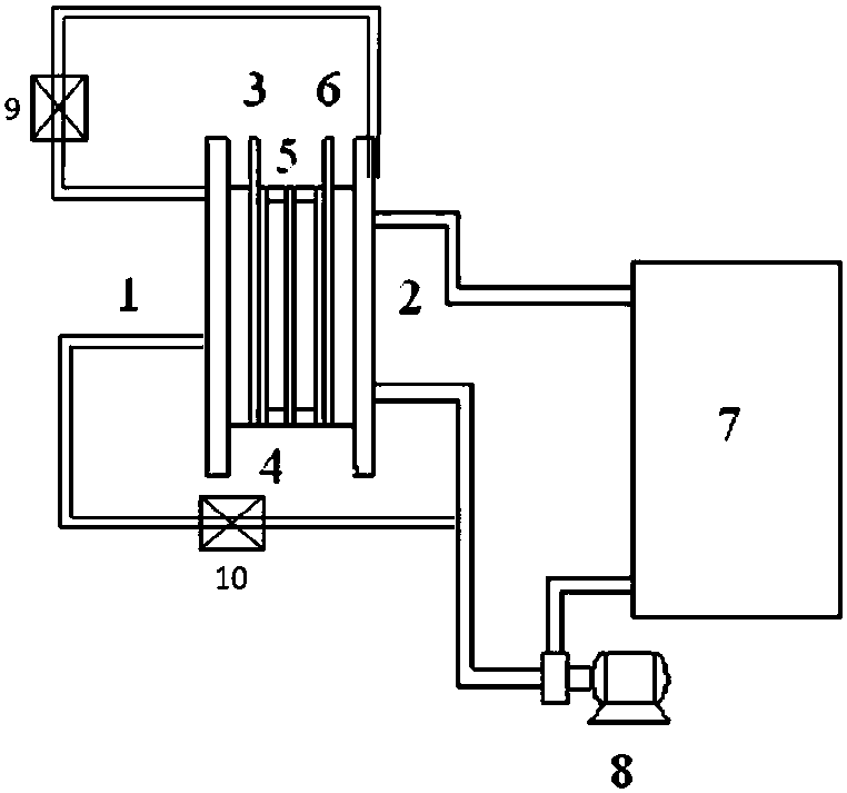
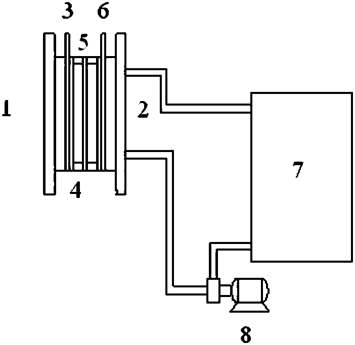
[0037] Such as figure 1 , The single cell sequentially includes a positive terminal plate, a positive current collector, a positive electrode (carbon felt), a PE porous membrane, a negative electrode, a negative current collector, and a negative terminal plate.
[0038] On the negative electrode electrolyte input pipeline between the negative electrode and the circulation pump, a branch pipeline is provided as the positive electrode electrolyte input pipeline, and the positive electrode electrolyte input pipeline is connected to the porous material of the positive electrode or the cavity between the positive electrode and the diaphragm;
[0039] On the negative electrode electrolyte output pipeline, a branch pipeline is p...
Embodiment 2
[0044] 1) Three carbon felts of 4x4x0.5cm are used for the positive electrode, and one carbon felt of 4x4x0.5cm is used for the negative electrode
[0045] 2) Prepare 60ml of 2mol / L zinc bromide solution for use.
[0046] Battery assembly and operation mode is the same as embodiment 1
[0047] The single cell sequentially includes a positive terminal plate, a positive current collector, a positive electrode, a Nafion117 membrane, a negative electrode, a negative current collector, and a negative terminal plate.
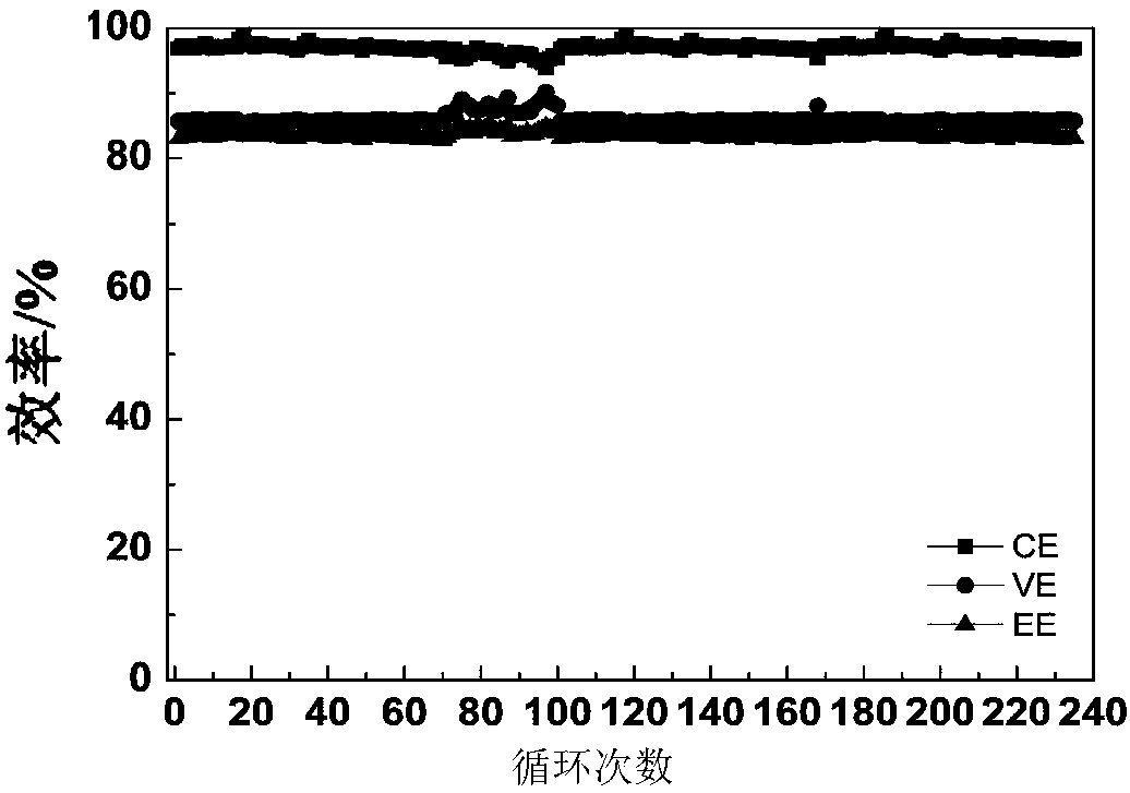
[0048] Depend on Figure 4 It can be seen that the electrode area of the battery is 36cm 2 , charge and discharge current density: 40mA / cm 2 , charging time 1.5h, battery coulombic efficiency: 96%, voltage efficiency: 86%, energy efficiency: 81%.
Embodiment 3
[0050] 1) Two carbon felts of 4x4x0.5cm are used for the positive electrode, and one carbon felt of 4x4x0.5cm is used for the negative electrode
[0051] 2) Prepare 60ml of 2mol / L zinc bromide solution for use.
[0052] Battery assembly and operation mode is the same as embodiment 1
[0053] The single cell sequentially includes a positive terminal plate, a positive current collector, a positive electrode, a PP porous membrane, a negative electrode, a negative current collector, and a negative terminal plate.
[0054] Depend on Figure 5 It can be seen that the electrode area of the battery is 36cm 2 , charge and discharge current density: 40mA / cm 2, charging time 2h, battery Coulomb efficiency: 94%, voltage efficiency: 86%, energy efficiency: 81%.
PUM
| Property | Measurement | Unit |
|---|---|---|
| Area | aaaaa | aaaaa |
| Charge and discharge current density | aaaaa | aaaaa |
Abstract
Description
Claims
Application Information
 - Generate Ideas
- Intellectual Property
- Life Sciences
- Materials
- Tech Scout
- Unparalleled Data Quality
- Higher Quality Content
- 60% Fewer Hallucinations
Browse by: Latest US Patents, China's latest patents, Technical Efficacy Thesaurus, Application Domain, Technology Topic, Popular Technical Reports.
© 2025 PatSnap. All rights reserved.Legal|Privacy policy|Modern Slavery Act Transparency Statement|Sitemap|About US| Contact US: help@patsnap.com