Energy-saving sump oil dehydration device and treatment method thereof

The technology of a dehydration device and a treatment method is applied in the treatment of hydrocarbon oil, the treatment of only multi-stage series refining process, the petroleum industry, etc. Evaporation area, improving economic efficiency, and easy operation

Active Publication Date: 2018-04-06
SHANGHAI YOUHUA PROCESS INTEGRATED TECH CO LTD +1
View PDF1 Cites 6 Cited by
  • Summary
  • Abstract
  • Description
  • Claims
  • Application Information

AI Technical Summary

Problems solved by technology

All the above methods have a certain dehydration effect, but there are also some problems, such as the dehydration effect cannot meet the refining requirements, the operation is complicated, the one-time investment is large, and the operation cost is high.

Method used


Image

  • Energy-saving sump oil dehydration device and treatment method thereof

Examples


Embodiment 1

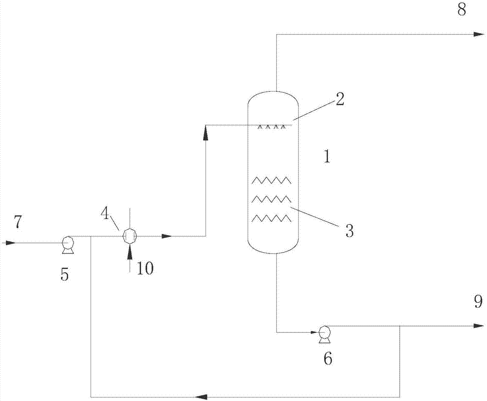
[0035] This embodiment provides an energy-saving waste oil dehydration device, such as figure 1As shown, the device includes a sewage oil dehydration tower 1, a sewage oil atomizer 2, a Venturi rod layer 3, a circulation heater 4, a sewage oil pump to be dehydrated 5 and a sewage oil circulation pump 6; wherein, the sewage oil pump to be dehydrated The inlet of 5 is connected to the sewage oil to be dehydrated 7 through a pipeline, the outlet of the sewage oil pump 5 to be dehydrated is connected to the cold flow inlet of the circulation heater 4, and the cold flow outlet of the circulation heater 4 is connected to the sewage oil dehydration tower 1, the heat flow inlet and outlet of the circulation heater 4 are connected with the heat source 10 of the circulation heater, the gas phase outlet of the waste oil dehydration tower 1 is connected with the oil gas pipeline 8 at the top of the fractionation tower, and the waste oil dehydration tower The liquid phase outlet of 1 is co...

Embodiment 2

[0041] This embodiment provides an energy-saving waste oil dehydration device. The device and its connection refer to Embodiment 1, the only difference is that the heat source 10 of the circulation heater is coked diesel oil in the refinery.

Embodiment 3

[0043] This embodiment provides a treatment method of an energy-saving waste oil dehydration device. The method is carried out using the device in Example 1. The specific treatment method includes the following steps:

[0044] (a) The waste oil to be dehydrated with a water content of 20% enters the waste oil atomizer 2 built into the waste oil dehydration tower 1 after being heated by the circulating heater 4 for atomization treatment, and the circulating heater 4 heats The temperature of the heat source 10 is 160°C;

[0045] (b) dehydrating the atomized waste oil obtained in step (a), the operating pressure is 0.1MPa, the operating temperature is 150°C, the obtained tower top product is subjected to fractionation treatment, and part of the obtained tower bottom waste oil is subjected to waste oil refining treatment , and another part returns to step (a) to mix with the waste oil to be dehydrated, and then enters the circulation heater 4 for heating.

[0046] In this embodim...


PUM


Abstract

The invention provides an energy-saving sump oil dehydration device and a treatment method thereof. The energy-saving sump oil dehydration device comprises a sump oil dehydration tower, a sump oil atomizer, a Venturi rod layer, a circulating heater, a pump for sump oil to be dehydrated and a circulating sump oil pump. A circulating heating and atomizing technologies are used; low-temperature afterheat of an oil refining device is fully utilized; heated sump oil is atomized into fine fogdrop, so that the oil-water boundary tension is reduced; the oil-water evaporation area is increased; the deep dehydration of the sump oil is realized. The energy-saving sump oil dehydration device has the advantages that the flow process is simple; the operation is simple and convenient; the energy consumption is low; the dehydration effect is good; the applicability is wide. The energy-saving sump oil dehydration device can be used for light sump oil dehydration, can also be used for heavy sump oil dehydration and is particularly applicable to deep dehydration of seriously emulsified sump oil; the water content in the sump oil can be lowered to 2 percent or less; the requirement of sump oil refining on the water content is met.

Description

technical field [0001] The invention belongs to the field of refinery waste oil treatment, and relates to an energy-saving waste oil dehydration device and a treatment method thereof. Background technique [0002] In the process of petroleum refining, all kinds of heavy dirty oil will be produced, such as salty sewage or oily sewage produced in the process of crude oil dehydration, oil tank water cutting and equipment purging and cleaning. After oil separation, flotation and Heavy dirty oil formed after coalescence. These heavy dirty oils have the characteristics of complex components, many impurities, serious emulsification, high water content and difficult removal of water. Sent to the device for refining, some choose as fuel oil for personal use or takeaway. Among them, the dirty oil sent to the unit for re-refining will have the problem of affecting the safe and stable operation of the unit due to high water content; and the dirty oil for self-use or takeaway has the p...

Claims


Application Information

Patent Timeline
Patent Type & Authority Applications(China)
IPC IPC(8): C10G53/02
CPCC10G53/02C10G2300/1003
Inventor 余金森孙虎良马素娟刘吉顺李柏
Owner SHANGHAI YOUHUA PROCESS INTEGRATED TECH CO LTD
Why Eureka
Try Eureka