Method and apparatus for multi-laser-beam-combined welding of glass material

A glass material and laser beam technology, applied in glass forming, glass remolding, glass manufacturing equipment, etc., can solve the problems of inability to form welds, low adhesive strength performance, and reduced sealing performance, and improve welding performance. Good effect on efficiency, strength and sealing performance

Pending Publication Date: 2018-04-10
HUAZHONG UNIV OF SCI & TECH
View PDF6 Cites 14 Cited by
  • Summary
  • Abstract
  • Description
  • Claims
  • Application Information

AI Technical Summary

Problems solved by technology

Although adhesives can connect different materials, adhesive packaging has the following problems: first, the release of gas from the adhesive will cause contamination of surrounding devices, resulting in damage to chip performance; Decreased stability; finally, under the condition of undergoing huge temperature changes, the thermal degradation of the adhesive and the stress accumulation of thermal expansion will reduce the service life of the adhesive, resulting in a decrease in the life of the chip, and the adhesive bond strength performance is low, which cannot be used for high strength requirements. Application requirements in aerospace and other fields
[0007] However, at present, this method of ultrashort pulse laser micro-welding glass melts very little glass material, which cannot fill a large welding gap; and increasing the pulse energy will cause the pulse peak power density to be too high and form an etching removal material effect. The glass material is partially broken and a good weld cannot be formed, so the quality requirements for the flatness and smoothness of the glass surface are very high, and the glass must be fixed and clamped with a clamp so that the gap between the two pieces of glass is less than a quarter Only when the wavelength (or 100nm) reaches the optical contact, and the short focal length objective lens is used for focusing and welding, can the welding be successful
This method also has the disadvantages of strict requirements on the focus position and fluctuation, and the welding must be realized by moving the workbench. The speed can only be maintained at a few millimeters per second, and the efficiency is too low. It is difficult to realize engineering applications.

Method used


Image

  • Method and apparatus for multi-laser-beam-combined welding of glass material
  • Method and apparatus for multi-laser-beam-combined welding of glass material

Examples


example 1

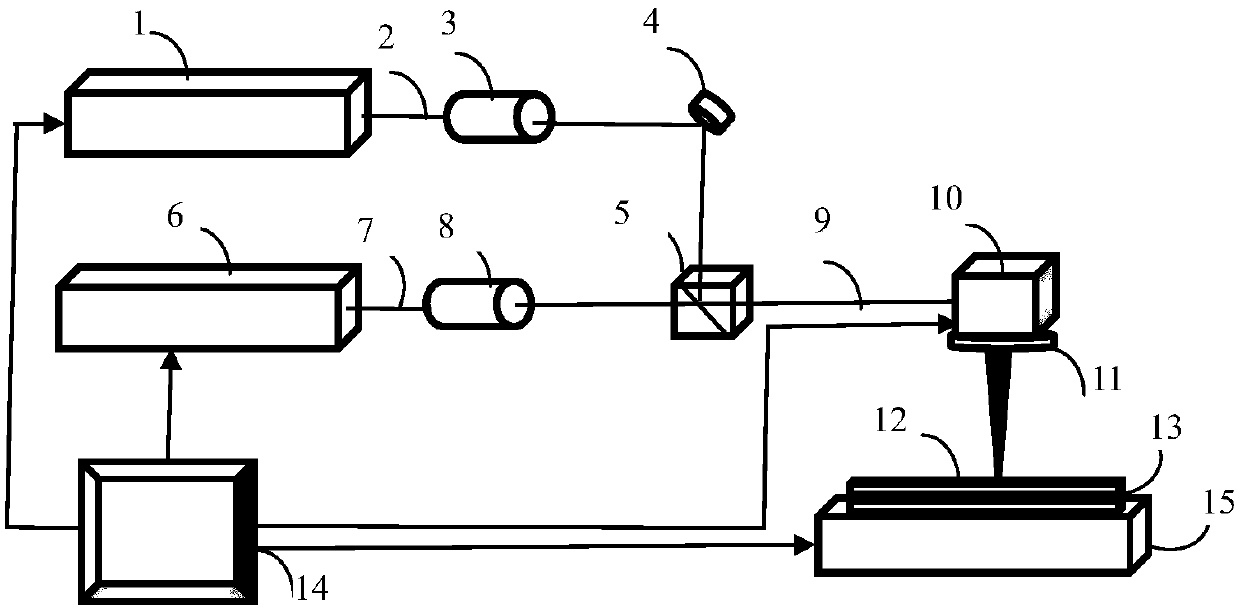
[0024] Example 1: Using such figure 1 The first multi-laser beam combined processing equipment shown uses an ultra-short-second pulse laser with a pulse width of 10 picoseconds, a wavelength of 1064 nm and a laser beam output in the P polarization direction, and a laser beam with a wavelength of 1064 nm and an output laser beam in the S polarization direction. Continuous fiber laser. The output power and repetition frequency of the ultra-short-second pulse laser are 15W and 10MHz, respectively, the output power of the continuous fiber laser is 10W, and the scanning speed of the galvanometer is 1000mm / s. The distance between the two pieces of soda lime glass is 8μm, and the focal point of the combined laser beam is at the contact position between the two pieces of soda lime glass, and galvanometer scanning welding is performed to obtain a weld with good sealing and strength.

example 2

[0025] Example 2: Using such figure 1 The first multi-laser beam combined processing equipment shown uses an ultra-short-second pulse laser with a pulse width of 10 picoseconds, a wavelength of 1064 nm and a laser beam output in the P polarization direction, and a laser beam with a wavelength of 1064 nm and an output laser beam in the S polarization direction. Continuous fiber laser. The output power and repetition frequency of the ultra-short-second pulse laser are 20W and 10MHz, respectively, the output power of the continuous fiber laser is 25W, the scanning speed of the galvanometer is 1000mm / s, the distance between two pieces of quartz glass is 12μm, and the focus point of the combined laser beam is located at two At the contact position between the pieces of quartz glass, galvanometer scanning welding is performed to obtain a weld with good sealing and strength.

example 3

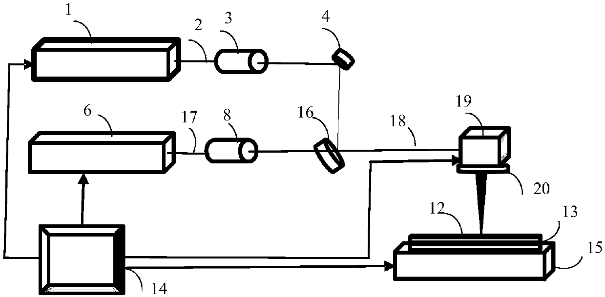
[0026] Example 3: Using such figure 2 The second multi-laser beam combined processing equipment shown uses an ultra-short-second pulse laser with a pulse width of 10 picoseconds, a wavelength of 532nm and a laser beam output in the P polarization direction, and a wavelength of 1064nm and a laser beam output in any polarization direction. Continuous fiber laser. The output power and repetition frequency of the ultra-short-second pulse laser are 10W and 10MHz, respectively, the output power of the continuous fiber laser is 20W, the scanning speed of the galvanometer is 1000mm / s, the distance between two pieces of white glass is 10μm, and the focus point of the combined laser beam is located at two At the contact position between the pieces of white glass, the galvanometer scan and the worktable are welded in parallel mode to obtain a large area of ​​sealing and good strength weld.


PUM


Abstract

The invention discloses a method and apparatus for multi-laser-beam-combined welding of a glass material. According to the invention, laser beams emitted by an ultrafast pulsed laser and including glass-transmitting light and laser beams emitted by a continuous laser or long-pulse laser and including glass-transmitting light are combined onto a same optical axis and are then focused on the contact-making part of two pieces of glass by a scanning galvanometer and a field-scanning focusing mirror; the ultrafast pulsed laser beams produce non-linear absorption effect in the two pieces so as to allow the glass material in areas beside a focal point to be fused; the fused glass material has substantially improved absorptivity on continuous or long-pulse laser due to changes in absorptivity; more fused glass materials are produced through further inputting of energy so as to fill welding gaps and to eradicate etching effect, so welding of the area where the focal point is located is finished; and the glass material is scanned and welded until welding operation is finished. The method and apparatus provided by the invention can improve laser beam welding efficiency and can be applied through engineering approaches.

Description

Technical field [0001] The invention belongs to the technical field of laser processing applications, and specifically relates to a method and equipment for welding glass materials by combining multiple laser beams. Background technique [0002] Glass materials are excellent materials for the production of chip packaging such as implanted microelectronics, solar cells, organic light-emitting diodes (OLED), micro-electromechanical systems (MEMS), micro sensors and converters, and optoelectronic devices. Glass-encapsulated electronic chips are used in Various applications that sense key safety factors such as rotation, acceleration, and pressure have extremely broad and potential application value and market prospects in the automotive, train and other transportation industries, as well as in aerospace and other fields. For example, in space, soldered objects, including image sensors with packaged chip devices, must maintain a high degree of reliability and airtightness even under ...

Claims


Application Information

Patent Timeline
IPC IPC(8): C03B23/20C03B23/24C03B23/203
CPCC03B23/20C03B23/203C03B23/24
Inventor 段军陈航张菲曾晓雁
Owner HUAZHONG UNIV OF SCI & TECH
Why Eureka
Try Eureka