A kind of frp combined micropile and manufacturing method

A manufacturing method and technology of micropile, which is applied in the direction of sheet pile wall, building, foundation structure engineering, etc., can solve the problems of increasing technical difficulty and engineering cost, insufficient performance, increasing cross-sectional area of ​​steel bar or section steel, etc. , to achieve the effect of strong compression and horizontal resistance, close deformation modulus, and improved corrosion resistance

Active Publication Date: 2019-07-16
连云港智源电力设计有限公司
View PDF10 Cites 0 Cited by
  • Summary
  • Abstract
  • Description
  • Claims
  • Application Information

AI Technical Summary

Problems solved by technology

[0004] However, since the two materials that make up the micropile are steel and cement paste / concrete, steel is a corrosive material with poor corrosion resistance, while cement-based paste and concrete are both brittle materials that are prone to cracking when subjected to tension and are difficult to install. Form effective protection for steel bars or section steel; in addition, the deformation moduli of the two materials are quite different, so that there is a problem of deformation inconsistency between the two when they are deformed by force, and the performance of the two materials has not been fully utilized; again , increasing the cross-sectional area of ​​steel or section steel can neither fundamentally solve the corrosion problem, but also increase the cost; while coating the surface of steel bar or section steel with an anti-corrosion layer, or wrapping a corrosion-resistant polymer sheath, increases the cost of corrosion at the same time. Technical difficulty and engineering cost, and once the protective layer is damaged during construction, it cannot be repaired on site

Method used


Image

  • A kind of frp combined micropile and manufacturing method
  • A kind of frp combined micropile and manufacturing method
  • A kind of frp combined micropile and manufacturing method

Examples


Embodiment Construction

[0038] The following will clearly and completely describe the technical solutions in the embodiments of the present invention with reference to the accompanying drawings in the embodiments of the present invention. Obviously, the described embodiments are only some, not all, embodiments of the present invention. Based on the embodiments of the present invention, all other embodiments obtained by persons of ordinary skill in the art without making creative efforts belong to the protection scope of the present invention.

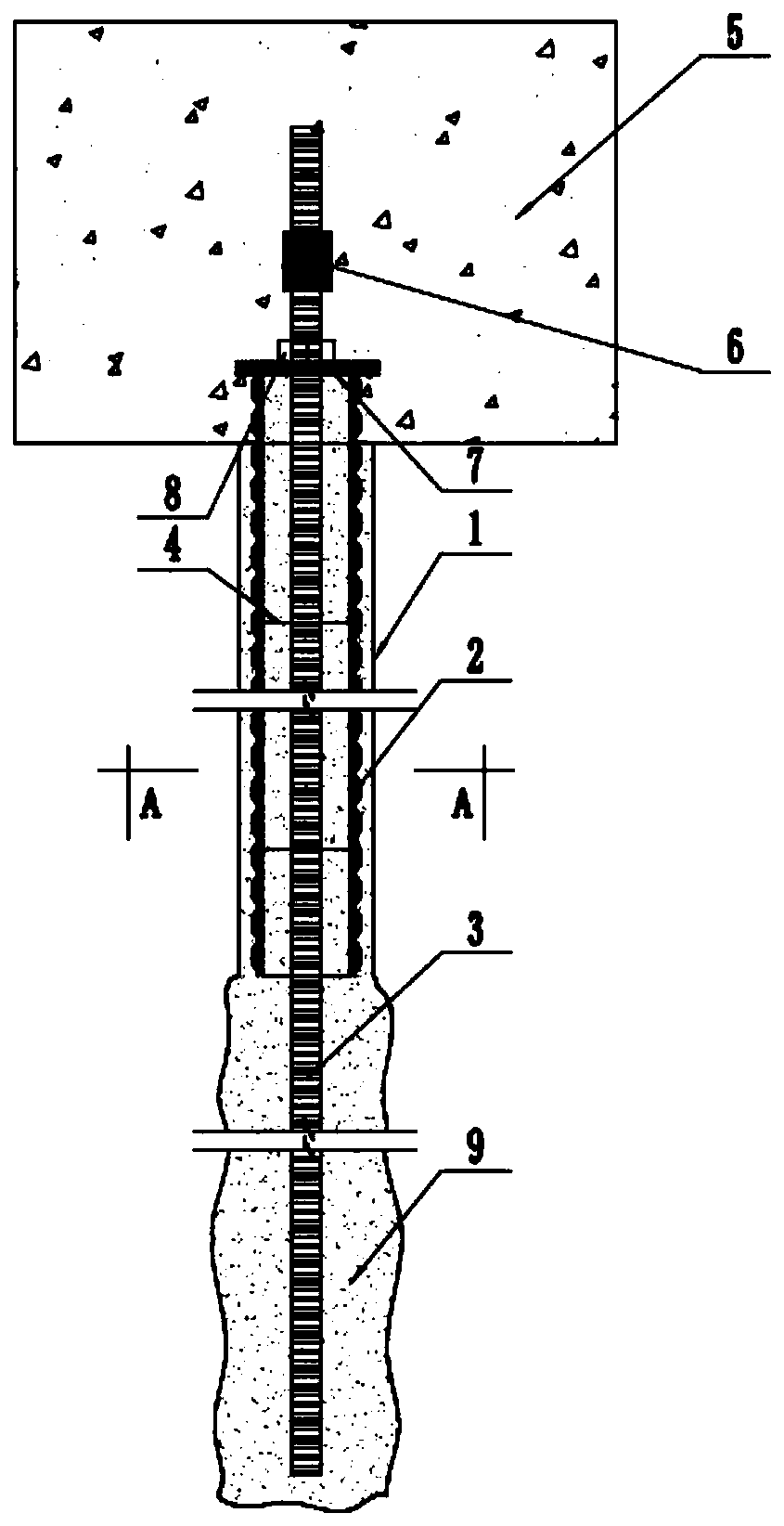
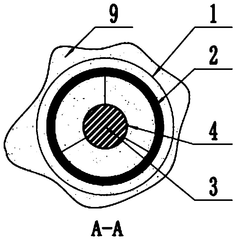
[0039] The purpose of the present invention is to provide a FRP combined micro-pile and its manufacturing method to solve the problems in the prior art and significantly improve the corrosion resistance and bearing capacity of the pile foundation.

[0040] In order to make the above objects, features and advantages of the present invention more comprehensible, the present invention will be further described in detail below in conjunction with the accompanying d...


PUM


Abstract

The invention discloses an FRP composite micro pile and a manufacturing method and relates to the technical field of engineering pile foundations. The FRP composite micro pile comprises an FRP pipe, an FRP rib and a concrete foundation; a through hole is formed in the FRP pipe; the FRP rib is arranged in the through hole and penetrates the FRP pipe; the FRP rib is connected with the FRP pipe through a positioning ring; the top end of the FRP pipe is connected with the concrete foundation; the FRP pipe is used for being vertically installed in a cavity of a pile hole; and the cavity of the pilehole and the through hole of the FRP pipe are used for casting grouting. According to the FRP composite micro pile and the manufacturing method, an FRP material is used for replacing a traditional rebar or structural steel, and the FRP material and cured cement-based slurry form a pile body; and the FRP material has extremely high corrosion resistant capacity, excellent mechanical performance andgood machinability, the FRP material has similar deformation modulus with the cement-based slurry, the FRP material and the cement-based slurry can achieve collaborative work, the respective performance is given full play to, and the corrosion resistant performance and the bearing performance of the pile foundation are remarkably improved.

Description

technical field [0001] The invention relates to the technical field of engineering pile foundations, in particular to an FRP composite micro pile and a manufacturing method thereof. Background technique [0002] Micro-piles refer to bored piles with a diameter of no more than 300mm and built-in reinforcing materials. Usually, pressure grouting is required to improve their bearing performance. At present, there are two main methods of manufacturing micro piles at home and abroad. One is to build a single large-diameter high-strength steel bar or section steel in the borehole, and then perform pressure grouting in the hole. The grouting fluid is mostly cement grout. The method is common in foreign countries; the other is to use multiple steel bars to form a steel cage instead of the above-mentioned single steel bar or section steel, and then cast stones in the holes for grouting or directly pour fine stone concrete (including grouting materials), this method is commonly used i...

Claims


Application Information

Patent Timeline
Patent Type & Authority Patents(China)
IPC IPC(8): E02D5/38E02D15/04
CPCE02D5/38E02D15/04
Inventor 宗钟凌吕凤伟武江传宋明志李青松
Owner 连云港智源电力设计有限公司
Why Eureka
Try Eureka