Device for treating high-temperature tail gas of graphite production

A technology for exhaust gas treatment and treatment device, which is applied in the direction of gas treatment, gaseous discharge wastewater treatment, combined device, etc., can solve problems such as unenvironmental exhaust methods, save the cost of exhaust gas treatment, reduce usage, and ensure long-term recycling. Effect

Inactive Publication Date: 2018-05-08
成都纽扣互动科技有限公司
View PDF0 Cites 2 Cited by
  • Summary
  • Abstract
  • Description
  • Claims
  • Application Information

AI Technical Summary

Problems solved by technology

[0003] In the process of producing graphite with needle coke, high-temperature sintering is an essential and important process, because the material composition in needle coke is extremely complex, so the composition of tail gas after high-temperature sintering is complex, containing a large amount of harmful gases and gaseous Oily substances, such as vulcanized gas and gaseous asphalt, the existing treatment process is to install a very long pipeline at the exhaust gas outlet of the high-temperature sintering furnace, and pass the high-temperature gas into the pipeline. With the transportation of the pipeline, the gaseous substances condense and pile up. In the pipeline, other substances are discharged at will. Under the increasingly stringent requirements of the country for environmental protection, this unenvironmentally friendly exhaust method will be banned. Therefore, it is necessary to develop a high-temperature sintering furnace exhaust gas for graphite production. processing device

Method used


Image

  • Device for treating high-temperature tail gas of graphite production
  • Device for treating high-temperature tail gas of graphite production
  • Device for treating high-temperature tail gas of graphite production

Examples


Embodiment Construction

[0023] The following will clearly and completely describe the technical solutions in the embodiments of the present invention with reference to the accompanying drawings in the embodiments of the present invention. Obviously, the described embodiments are only some, not all, embodiments of the present invention. Based on the embodiments of the present invention, all other embodiments obtained by persons of ordinary skill in the art without making creative efforts belong to the protection scope of the present invention.

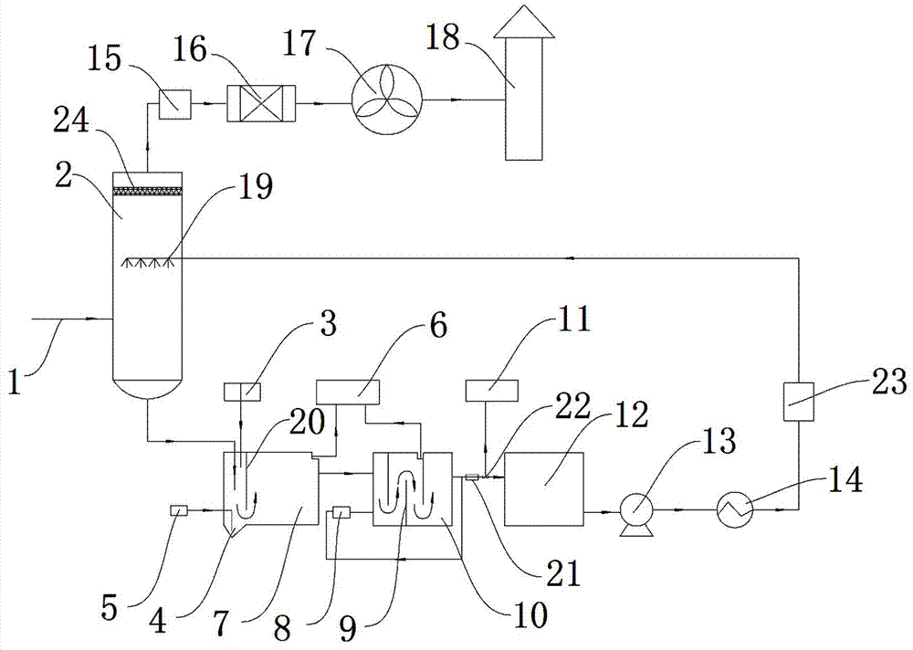
[0024] Such as figure 1 As shown, a graphite production high-temperature tail gas treatment device, which includes a spray tower 2, a water circulation treatment device and an exhaust device, the spray tower 2 is equipped with an air inlet pipe 1, and the top of the inner chamber of the spray tower is provided with a demister 24. The high-temperature tail gas from the high-temperature sintering furnace enters the bottom of the spray tower 2 through the intake ...


PUM


Abstract

The invention discloses a device for treating high-temperature tail gas of graphite production. A gas inlet pipe is arranged on a spraying tower; a water circulation treatment device comprises a settling pond, an air flotation pond, a primary recovering pond, a clean water pond, a spraying pump and a spraying pipe; the water outlet end of the spraying tower is communicated with the water inlet endof the settling pond; a flocculating tank for adding a flocculating agent into the settling pond is arranged on one side of the settling pond; the first outlet of the settling pond is communicated with the primary recovering pond; the second outlet of the settling pond is communicated with the air flotation pond; the first outlet of the air flotation pond is communicated with the primary recovering pond; the second outlet of the air flotation pond is communicated with the clean water pond; and the water inlet of the spraying pump is communicated with the clean water pond. The device for treating high-temperature tail gas of graphite production has the following beneficial effects: the device can treat the high-temperature tail gas with complex and changeable components in the production process of the graphite, so the universality of the device is improved and the device is not constrained by the raw materials; furthermore, the whole treatment process is physical treatment and condensate water can be recycled, so that the treatment device is energy-saving and environment-friendly.

Description

technical field [0001] The invention relates to the technical field of graphite production, in particular to a high-temperature tail gas treatment device for graphite production. Background technique [0002] Needle coke is the main raw material for producing high-power (HP) and ultra-high-power (UHP) graphite electrodes, and it can be divided into petroleum-based needle coke and coal-based needle coke. Due to the good graphitization performance of needle coke, the HP and UHP graphite electrodes produced by it have excellent electrical and thermal conductivity, thermal shock resistance and oxidation resistance, which can meet the requirements of high current density in large-capacity electric arc furnaces and rapid cooling. In the rapid heating state, there are high mechanical strength and other smelting quality requirements, which are incomparable in terms of performance of graphite electrodes produced by ordinary coke. [0003] In the process of producing graphite with ne...

Claims


Application Information

Patent Timeline
Patent Type & Authority Applications(China)
IPC IPC(8): B01D53/18B01D53/00B01D53/26B01D50/00C02F9/04C02F103/18
CPCB01D53/002B01D53/1425B01D53/18B01D53/185B01D53/26C02F9/00C02F2103/18C02F2209/00C02F1/40C02F1/24C02F1/66C02F1/5281B01D2258/02B01D2252/103B01D50/60
Inventor 刘念邱陈越陈鹏
Owner 成都纽扣互动科技有限公司
Why Eureka
Try Eureka