Zero discharging system and method for landfill leachate

A landfill leachate, zero-discharge technology, applied in chemical instruments and methods, sedimentation treatment, water/sewage multi-stage treatment, etc. Possibility of contamination, effect of increasing water production rate, reducing water withdrawal

Inactive Publication Date: 2018-05-08
CHONGQING SANFENG ENVIRONMENTAL IND GRP +1
View PDF3 Cites 5 Cited by
  • Summary
  • Abstract
  • Description
  • Claims
  • Application Information

AI Technical Summary

Problems solved by technology

At present, most of the landfill leachate treatment systems adopt the discharge process, that is, after the landfill leachate is treated, the treated water is discharged through the standard outlet; however, the current leachate treatment adopts a discharge standard with low water quality indicators. Due to the reuse water standard (that is, the treatment process using the discharge standard cannot meet the reuse water standard), the direct discharge is affected by the receiving water body (that is, there must be a receiving water body around the leachate treatment system that can receive the leachate clear liquid discharge), and the impact on the leachate The selection of the filtrate treatment station has a great influence; and the direct discharge of the leachate clear liquid will cause a waste of energy, especially for the incineration plant (the water in the incineration plant needs to be charged)
Therefore, it is necessary to design a new type of landfill leachate zero-discharge industry to solve the problems of low water production rate, low water output index requirements, large concentrated liquid output, site selection is limited by the receiving water body, and clear liquid is directly discharged in the existing technology. cause a lot of energy waste

Method used


Image

  • Zero discharging system and method for landfill leachate

Examples


Embodiment Construction

[0019] Embodiments of the present invention are described below through specific examples, and those skilled in the art can easily understand other advantages and effects of the present invention from the content disclosed in this specification. The present invention can also be implemented or applied through other different specific implementation modes, and various modifications or changes can be made to the details in this specification based on different viewpoints and applications without departing from the spirit of the present invention. It should be noted that the diagrams provided in the following embodiments are only schematically illustrating the basic concept of the present invention, and the following embodiments and the features in the embodiments can be combined with each other in the case of no conflict.

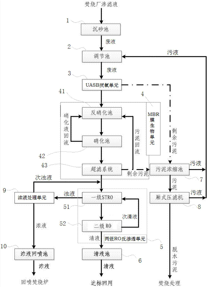
[0020] The embodiment is basically as shown in the accompanying drawings: this embodiment provides a system for zero discharge of landfill leachate, and the s...


PUM


Abstract

The invention discloses a zero discharging system and method for landfill leachate, and belongs to the field of wastewater treatment. The system is provided with a settling tank, an adjustment basin,a UASB (upflow anaerobic sludge blanket) anaerobic unit, an MBR (membrane bioreactor) membrane biological unit, a two-stage RO (reverse osmosis) unit and a clear liquid basin in sequence according toa zero discharging treatment sequence of the landfill leachate. The settling tank is connected with the leachate of an incineration plant, and is used for performing solid-liquid separation on the landfill leachate; the adjustment basin is used for homogenizing separated waste liquid; the UASB anaerobic unit is used for performing an anaerobic reaction on the homogenized waste liquid; the MBR membrane biological unit is used for performing a membrane biological reaction on the waste liquid subjected to the anaerobic reaction; and clear liquid filtered by the two-stage RO unit enters the clearliquid basin for storage for repeated use again. The zero discharging system disclosed by the invention is high in water yield and low in concentrated liquid yield, has a strict requirement on an effluent index, and cannot be affected by received water body; by reuse of the clear liquid, a large amount of energy is saved; and the operation is stable, and the environmental friendliness risk for leachate treatment is reduced.

Description

technical field [0001] The invention belongs to the technical field of wastewater treatment, and relates to a system and method for zero discharge of landfill leachate. Background technique [0002] The water crisis caused by the shortage of water resources and water environment pollution has always been an important factor restricting the economic and social development of our country. The deterioration of water environment quality and the rapid development of economy urgently require sewage resource technology suitable for the development of the times to alleviate the shortage of water resources. Therefore, various new and improved high-efficiency wastewater treatment processes and technologies have emerged as the times require. At present, most of the landfill leachate treatment systems adopt the discharge process, that is, after the landfill leachate is treated, the treated water is discharged through the standard outlet; however, the current leachate treatment adopts a...

Claims


Application Information

Patent Timeline
Patent Type & Authority Applications(China)
IPC IPC(8): C02F9/14
CPCC02F1/441C02F3/1268C02F3/2846C02F9/00C02F2001/007
Inventor 雷东徐代平喻本宏杨川余明锐刘洋吴太军
Owner CHONGQING SANFENG ENVIRONMENTAL IND GRP
Why Eureka
Try Eureka