
Intelligent tail gas photooxygenation pyrolysis device using cavitation liquid technology

A cracking device and liquid technology, applied in the field of intelligent tail gas photo-oxygen cracking device, can solve the problems of inability to control the processing power of ultraviolet equipment in real time, low level of intelligent control, substandard treatment of pollutants, etc., so as to avoid accidental discharge and improve treatment. Effects, processing effects to enhance the effect

Pending Publication Date: 2018-05-11
QINGDAO UNIV OF SCI & TECH
View PDF10 Cites 3 Cited by
  • Summary
  • Abstract
  • Description
  • Claims
  • Application Information

AI Technical Summary

Problems solved by technology

However, the intelligent control level of the above-mentioned technical scheme is very low, and the processing power of the ultraviolet equipment cannot be controlled in real time according to the concentration of pollutants, resulting in the waste of energy or the problem that the treatment of pollutants is not up to standard
In addition, the exhaust gas treated by ultraviolet equipment will cause secondary pollution caused by the discharge of pollutants with the flow of water mist in the gas due to the limitations of traditional wet post-treatment equipment (generally using scrubbers).

Method used


Image

  • Intelligent tail gas photooxygenation pyrolysis device using cavitation liquid technology
  • Intelligent tail gas photooxygenation pyrolysis device using cavitation liquid technology
  • Intelligent tail gas photooxygenation pyrolysis device using cavitation liquid technology

Examples


Embodiment Construction

[0030] The specific implementation of the present invention will be further described below in conjunction with the accompanying drawings.

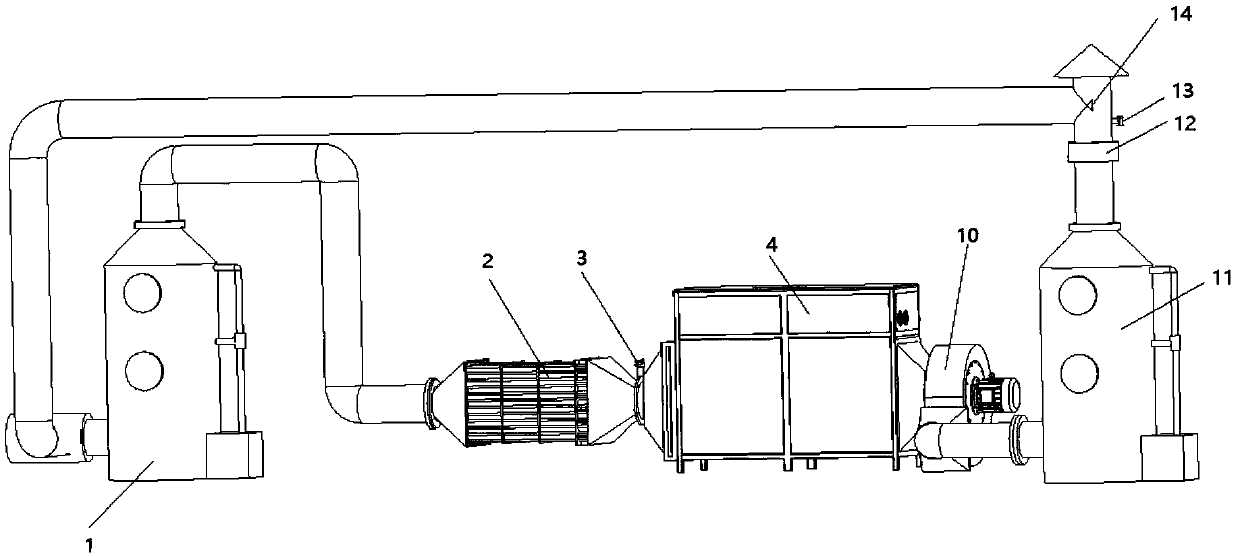
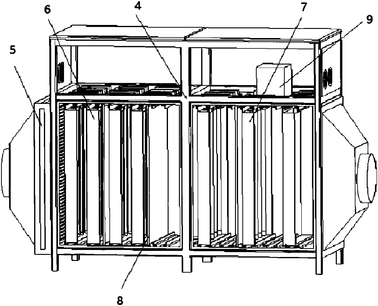
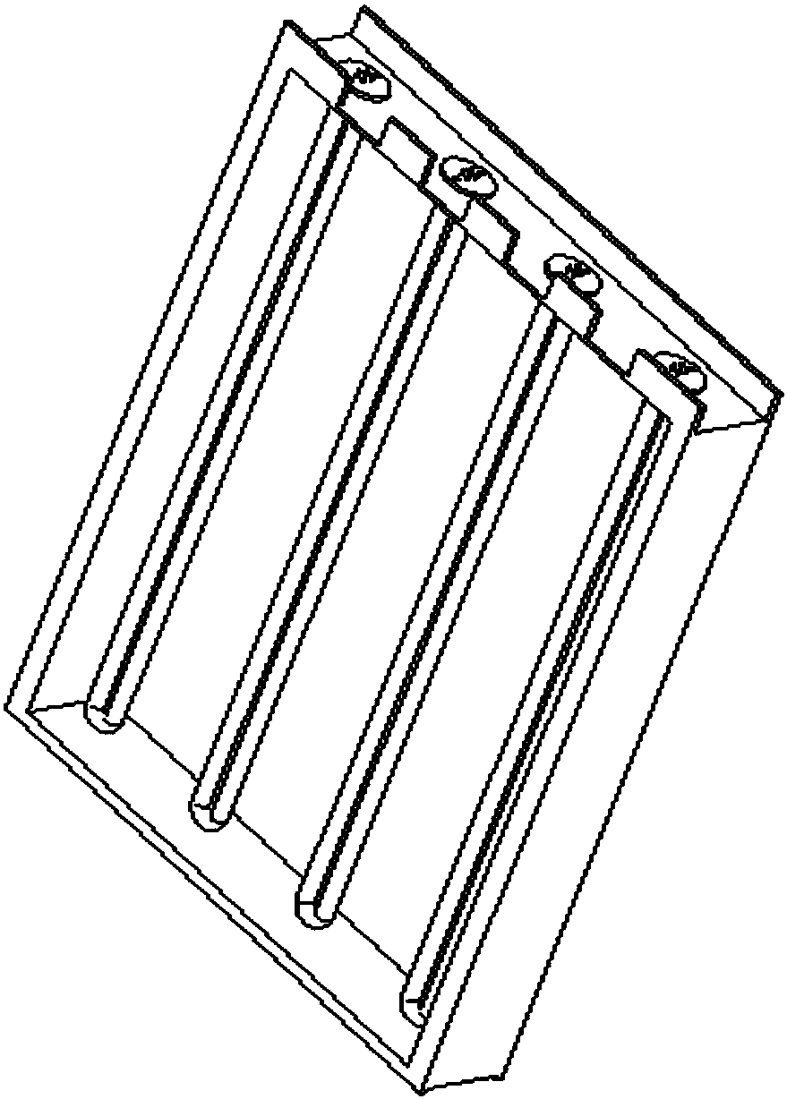
[0031] Such as figure 1 , 2 , 3 and 4, an intelligent tail gas photo-oxygen cracking device using cavitation liquid technology, including cavitation liquid waste gas washing device 1, oil and gas purification electric field equipment 2, waste gas concentration detection sensor 3, photo-oxygen cracking cabinet 4, anti- Dust filter wet net 5, high-energy ultraviolet light group module 6, ozone supply module 7, TiO 2 Catalytic net 8, single-chip microcomputer control system, negative pressure induced draft fan 10, dry flue gas comprehensive treatment tank 11, ozone filter screen 12; air inlet and exhaust port of cavitation liquid waste gas scrubber 1 and factory exhaust port and The oil and gas purification electric field equipment 2 are connected separately, the exhaust port of the oil and gas purification electric field equipment 2 is co...


PUM


Abstract

The invention discloses an intelligent tail gas photooxygenation pyrolysis device using a cavitation liquid technology. A cavitation liquid waste gas washing device is connected with an oil gas purifying electric field device through an air pipe. The oil gas purifying electric field device is connected with a photooxygenation pyrolysis cabinet through an air pipe. A waste gas concentration detecting sensor is installed at the inlet of the photooxygenation pyrolysis cabinet. A certain number of high-energy ultraviolet lamp group modules are installed in the photooxygenation pyrolysis cabinet atcertain intervals. A single-chip microcomputer control system is installed in an intelligent control cabinet. An induced draft fan is installed at the air outlet of the photooxygenation pyrolysis cabinet, and the air outlet of the negative pressure type induced draft fan is connected into a dry method smoke comprehensive processing tank. The single-chip microcomputer control system can control the combined switching on and switching off of the lamp group modules according to information fed back by the waste gas concentration detecting sensor. Energy-saving efficient running of the whole system can be achieved, the service life of the lamp group modules is prolonged, the organic waste gas processing effect is improved, a secondary pollution problem caused by a traditional wet method process is avoided, and super-clean emission is achieved.

Description

technical field [0001] This patent relates to the technical field of waste gas treatment, specifically an intelligent tail gas photo-oxygen cracking device using cavitation liquid technology. Background technique [0002] Air pollution is one of the most prominent environmental problems in my country at present. Among them, industrial waste gas is an important source of air pollutants. The most difficult to deal with in industrial waste gas is organic waste gas, which mainly includes various hydrocarbons, alcohols, aldehydes, acids, ketones and amines. They mainly come from the waste gas emitted during the production process of the petroleum and chemical industries. They are characterized by large quantities, large fluctuations in organic matter content, flammability, certain toxicity, and some have a foul smell. Domestic rubber factories, reclaimed rubber factories and other rubber-related industries also produce a large amount of organic waste gas during the production p...

Claims


Application Information

Patent Timeline
Patent Type & Authority Applications(China)
IPC IPC(8): B01D53/00B01D53/74B01D53/76B01D53/75B01D46/10
CPCB01D46/10B01D53/007B01D53/74B01D53/75B01D53/76B01D2258/02
Inventor 汪传生郭磊李海涛
Owner QINGDAO UNIV OF SCI & TECH
Learn More