
Cross-flow filtration oil-water separation device

An oil-water separation device and a technology of cross-flow filtration, which are applied in the directions of filtering and thickening suspension liquid separation, liquid separation, separation methods, etc., to achieve the effects of improving separation efficiency, simple operation and increasing contact area.

Pending Publication Date: 2018-05-18
北京北方科诚信息技术股份有限公司
View PDF0 Cites 1 Cited by
  • Summary
  • Abstract
  • Description
  • Claims
  • Application Information

AI Technical Summary

Problems solved by technology

[0004] In view of the shortcomings of the existing oil-water separation method and the limitations of the existing equipment in use, the present invention proposes a cross-flow filter oil-water separation device based on the optimization design of hydrophobic and lipophilic filter membrane materials and interface mechanics, which is based on interface mechanics and fluid The physical separation of mechanics has the characteristics of remarkable separation effect, convenient operation, low cost, easy engineering, and no secondary pollution. It is expected to be used for oil extraction, leakage during transportation, and oily sewage treatment produced by various industries. question

Method used


Image

  • Cross-flow filtration oil-water separation device
  • Cross-flow filtration oil-water separation device
  • Cross-flow filtration oil-water separation device

Examples


Embodiment

[0024] In this example, a stainless steel metal filter with a pore diameter of 30 μm is selected as the base material, and low surface energy materials such as hydrophobic silica and methyl MQ resin are selected to carry out surface hydrophobization modification treatment on the base material, and the hydrophobic silica Particles and MQ resin with low surface energy were fully dispersed in alcohol to obtain an alcohol mixed solution with a mass fraction of 1%. Soak the filter material in the mixed solution for 30 minutes, take it out and dry it in a vacuum oven at 100°C.

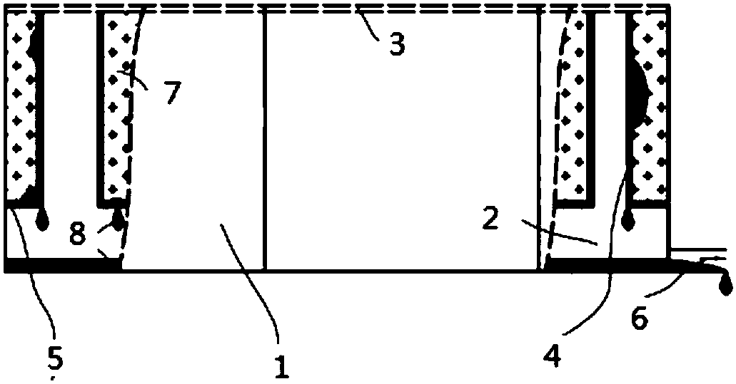
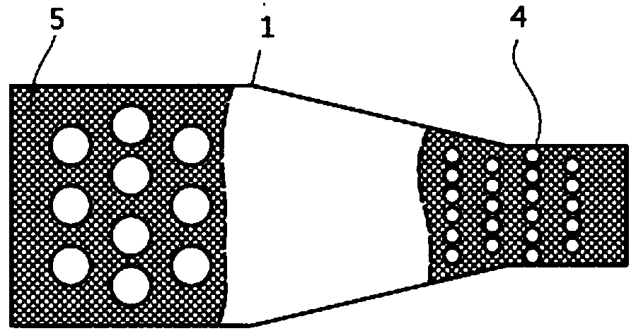
[0025] The overall length of the filter channel is 200mm, the width of the inlet is 50mm, the length of the converging part is 30mm, the width of the narrowest part of the converging part is 20mm, the width of the outlet is also 20mm, and the number of filter cartridges forming the microchannel is 20. The overall length of the cross-flow filter oil-water separation device is 200mm, the height is 60mm, and th...


PUM

PropertyMeasurementUnit
pore sizeaaaaaaaaaa
pore sizeaaaaaaaaaa
separationaaaaaaaaaa

Abstract

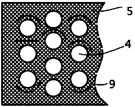
The invention discloses a cross-flow filtration oil-water separation device. The cross-flow filtration oil-water separation device comprises a filtering channel, wherein a cover body covers the top ofthe filtering channel; an oil collection groove is communicated with the bottom of the filtering channel; a plurality of filtering cartridges which are as high as the filtering channel are arranged in the filtering channel in a staggered manner; the bottoms of the filtering cartridges are communicated with the inner part of the oil collection groove; filtering screens are arranged at positions, which are not provided with the filtering cartridges, between the bottom of the filtering channel and the oil collection groove; the filtering screens have the performance that only oil can pass through the filtering screens, but water cannot pass through the filtering screens. The filtering channel is divided into a wide part, a converging part and a narrow part along a circulation direction of filtering; one end, close to an inlet, of the filtering channel forms the wide part; one end, close to an outlet, of the filtering channel forms the narrow part; the converging part is between the widepart and the narrow part; the oil collection groove and the cover body are molded in a manner of corresponding to shapes of the wide part, the converging part and the narrow part. According to the cross-flow filtration oil-water separation device disclosed by the invention, oil type substances in an oil-water mixture can rapidly enter the oil collection groove under the adsorption effect of a selective filtering material and the gravity effect, and oil-water separation is finished without the need of an external force effect; the cross-flow filtration oil-water separation device has the advantages of large application range, simple structure, high separation efficiency and wide application prospect.

Description

technical field [0001] The invention belongs to the technical fields of mechanical engineering, surface engineering, fluid mechanics and environmental engineering, and in particular relates to a cross-flow filter oil-water separation device. Background technique [0002] The random discharge of oily wastewater will cause oily substances to enter the water body and cause water quality deterioration, air pollution, crop production reduction, and ecological environment deterioration. At present, the treatment of oily wastewater has become an urgent problem to be solved. As an important means to solve oily wastewater, oil-water separation technology has attracted worldwide attention. For example, the process of oil extraction and refining, oil transportation and storage will generate oily wastewater, and oil extraction or oil tanker leakage will aggravate the generation of oily wastewater. Therefore, from environmental protection and other aspects, oil-water separation is of gr...

Claims


Application Information

Patent Timeline
Patent Type & Authority Applications(China)
IPC IPC(8): C02F1/40B01D17/02B01D17/032
CPCB01D17/0214B01D17/10C02F1/40
Inventor 王宝邢兵苏喜红
Owner 北京北方科诚信息技术股份有限公司
Learn More