Blast furnace

A blast furnace and furnace body technology, applied in blast furnaces, blast furnace details, blast furnace parts, etc., can solve problems such as potential safety hazards, insufficient purity of molten iron, difficulty in burning and melting iron ore, coke, and flux for slagging

Inactive Publication Date: 2018-05-22
XINCHANG SHENGXIA MACHINERY PLANT
View PDF0 Cites 3 Cited by
  • Summary
  • Abstract
  • Description
  • Claims
  • Application Information

AI Technical Summary

Problems solved by technology

[0003] The refractory brick layer of the existing blast furnace is directly built in the furnace body. Since the furnace body is designed in the shape of a pillar platform with a thin top and a thick bottom, and the refractory brick layer is in plane contact with the inner wall of the furnace, the refractory brick layer and the furnace body are in contact with each other. If the inner wall is not tightly connected, the refractory brick layer is likely to collapse as a whole, causing potential safety hazards. In addition, the iron ore, coke, and slag-making flux loaded from the top of the furnace during the ironmaking process are too fast to fall from the The time for the preheated air blown into the lower part of the furnace along the tuyeres around the furnace to contact with the iron ore, coke, and s

Method used


Image

  • Blast furnace
  • Blast furnace
  • Blast furnace

Examples


Embodiment Construction

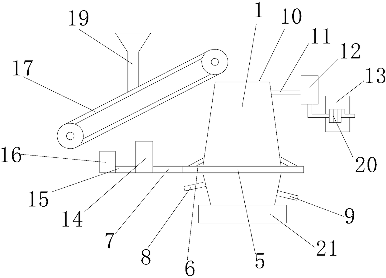
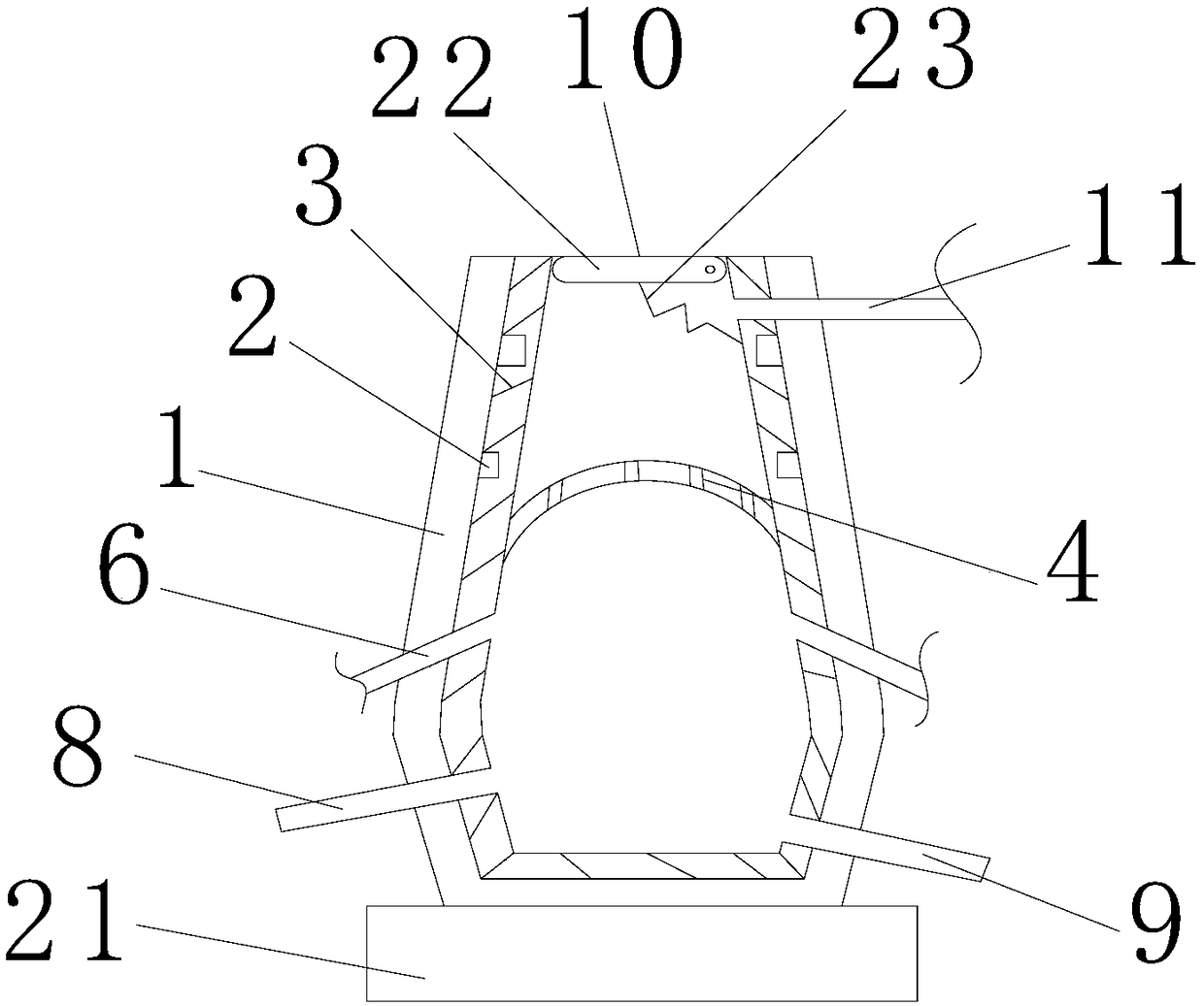
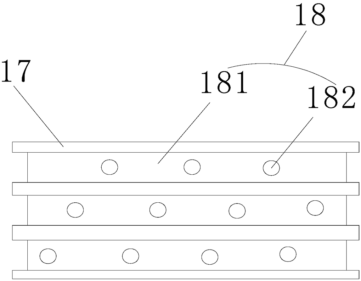
[0018] refer to figure 1 , 2, 3, a kind of blast furnace of the present invention, comprises furnace body 1, support plate 2, refractory brick layer 3, grate 4, ring furnace hot air pipe 5, hot air branch pipe 6, hot air pipe 7, slag outlet 8, tapping Port 9, feed port 10, waste gas pipe 11, dust collector 12, cooling water tank 13, hot blast stove 14, air intake pipe 15, blower 16, conveyor belt 17, storage tank 18, hopper 19, cooling pipe 20, furnace Seat 21, baffle plate 22 and spring 23, the side wall of the inner cavity of described furnace body 1 is fixedly provided with a plurality of supporting plates 2 from top to bottom, and the side wall of the inner cavity of described furnace body 1 is lined with refractory brick layer 3. The thickness of the refractory brick layer 3 is slightly larger than the width of the support plate 2 and wraps the support plate 2. The inner cavity of the furnace body 1 is fixed with a fire grate 4, and the outer part of the furnace body 1 i...


PUM


Abstract

The invention discloses a blast furnace. The blast furnace comprises a furnace body, supporting plates, a refractory brick layer, a fire gate, a ring-furnace hot air tube, a hot air branch tube, a hotair tube, a slag outlet, an iron outlet, a charge hole, a waste gas tube, a dust remover, a cooling water tank, a hot blast heater, a gas inlet tube, an air blower, a conveyor belt, a storage channeling slot, a discharge hopper, a cooling tube, a furnace base, a baffle plate and a spring, wherein the supporting plates are fixedly arranged on the side wall of the inner cavity of the furnace body from top to bottom; the side wall of the inner cavity of the furnace body is built with the refractory brick layer; the thickness of the refractory brick layer is a bit greater than width of the supporting plates and covers the supporting plates; the fire gate is fixedly arranged in the inner cavity of the furnace body; and the ring-furnace hot air tube is arranged on the outer side part of the furnace body. Compared with the prior art, the blast furnace has the advantages that connecting tightness between the refractory brick layer and the inner wall of the furnace body can be improved, raw material combusting and melting efficiency and effect are improved, in-batch feeding efficiency and effect of the raw materials are improved, energy consumption of a boiler is reduced, and environment-friendly performances of the blast furnace are improved.

Description

【Technical field】 [0001] The invention relates to the technical field of metal smelting equipment, in particular to a blast furnace. 【Background technique】 [0002] The blast furnace is made of steel plate as the furnace shell, and the shell is lined with refractory bricks. From top to bottom, the blast furnace body is divided into five parts: the furnace throat, the furnace body, the furnace waist, the furnace bosh, and the hearth. Due to the good technical and economic indicators of blast furnace ironmaking, simple process, large production capacity, high labor production efficiency, and low energy consumption, the iron produced by this method accounts for the vast majority of the world's total iron production. Blast furnaces are used to smelt pig iron and castings. The main equipment for iron and steelmaking. After the reduction reaction in the blast furnace, the iron ore is reduced to metallic iron. At this time, the state of the iron is a molten iron and slag. Metal ...

Claims


Application Information

Patent Timeline
IPC IPC(8): C21B7/06C21B7/02C21B7/00C04B35/103C04B35/63
CPCC21B7/06C04B35/103C04B35/6303C04B2235/3418C04B2235/3804C04B2235/3826C04B2235/402C04B2235/428C04B2235/447C04B2235/5208C21B7/002C21B7/02
Inventor 俞小夏军
Owner XINCHANG SHENGXIA MACHINERY PLANT
Why Eureka
Try Eureka