
Circularly polarized microstrip antenna and wireless device

A technology of circularly polarized antenna and microstrip line, which is applied in the direction of antenna, antenna grounding device, antenna grounding switch structure connection, etc., and can solve the problem of complex microstrip circularly polarized antenna structure, poor circular polarization performance, and slow simulation speed problems, to achieve the effect of reducing simulation burrs, increasing gain, and reducing processing difficulty

Pending Publication Date: 2018-05-25
GUANGDONG UNIV OF TECH
View PDF0 Cites 3 Cited by
  • Summary
  • Abstract
  • Description
  • Claims
  • Application Information

AI Technical Summary

Problems solved by technology

[0005] The purpose of the present invention is to provide a microstrip circularly polarized antenna, which can simultaneously overcome the shortcomings of the microstrip circularly polarized antenna, such as complex structure, difficult processing, slow simulation speed and poor circular polarization performance.

Method used


Image

  • Circularly polarized microstrip antenna and wireless device
  • Circularly polarized microstrip antenna and wireless device
  • Circularly polarized microstrip antenna and wireless device

Examples


Embodiment Construction

[0029] The following will clearly and completely describe the technical solutions in the embodiments of the present invention in conjunction with the accompanying drawings in the embodiments of the present invention. Obviously, the described embodiments are only some of the embodiments of the present invention, not all of them. Based on the embodiments of the present invention, all other embodiments obtained by persons of ordinary skill in the art without making creative efforts belong to the protection scope of the present invention.

[0030] The object of the present invention is to provide a microstrip circularly polarized antenna, which can simultaneously overcome the disadvantages of the microstrip circularly polarized antenna, such as complex structure, difficult processing, slow simulation speed and poor circular polarization performance.

[0031] In order to enable those skilled in the art to better understand the technical solution of the present invention, the present...


PUM

PropertyMeasurementUnit
Lengthaaaaaaaaaa
Widthaaaaaaaaaa
Lengthaaaaaaaaaa

Abstract

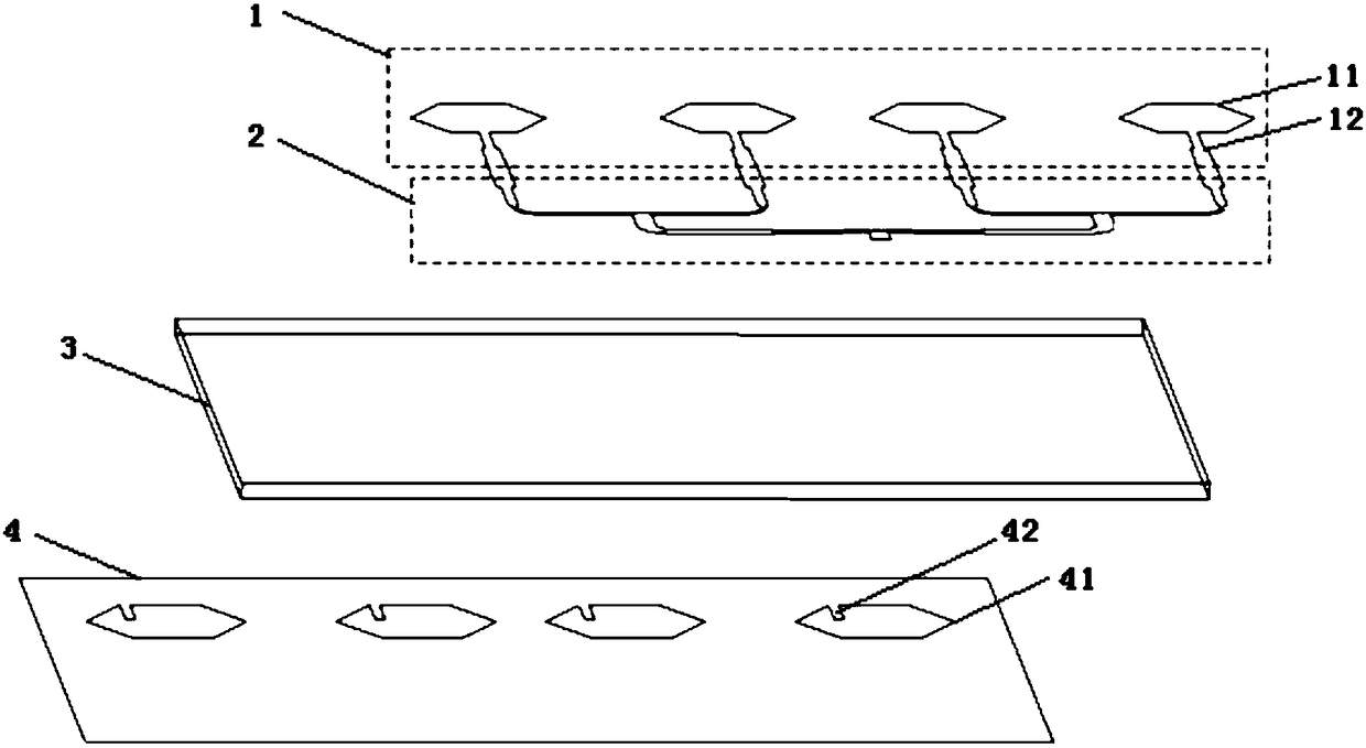
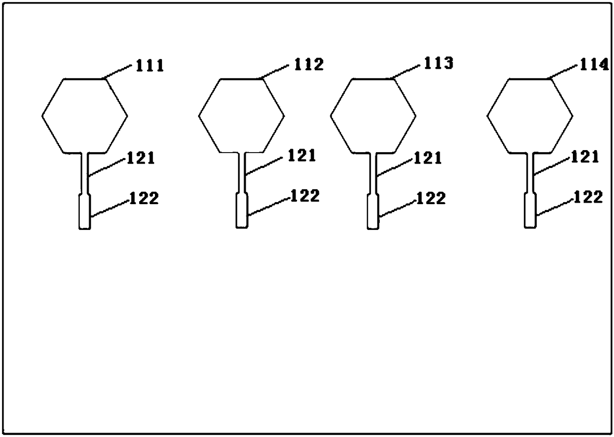
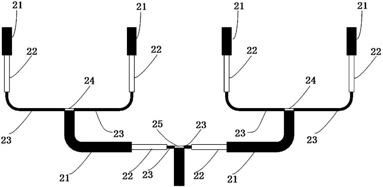
The invention discloses a circularly polarized microstrip antenna which comprises a patch array, a feed network, a substrate, and a floor. One face of the substrate is provided with a regular N-polygon metal patch which is in single-point connection with an array microstrip line. When voltage is introduced to the feed network, positive charges gather on the regular N-polygon metal patch, two degenerate modes with orthogonal polarization, equal amplitude and a certain phase difference can be generated. Negative charges gather on the edge of a regular N-polygon hole in the floor on the other face of the substrate, which forms capacitance load with the regular N-polygon metal patch. A rectangular patch plays the roles of increasing propagation path of current and increasing impedance and forms inductance load with a regular N-polygon metal patch coupling short circuit. Separation of resonant frequencies of the two degenerate modes is generated, the impedance phase angle of one mode leadsby 45 degrees, and the impedance phase angle of the other mode lags by 45 degrees, and circularly polarized radiation is formed. The circularly polarized microstrip antenna has the advantages of beingsimple in structure, easy to integrate, process and develop, good in circular polarization performance, and the like.

Description

technical field [0001] The invention relates to the field of wireless communication, in particular to a microstrip circularly polarized antenna and a wireless device. Background technique [0002] The antenna is a transformer that can convert the guided wave propagating on the transmission line into an electromagnetic wave propagating in free space, or on the contrary, it plays an important role in transmitting or receiving electromagnetic waves in radio equipment. Circularly polarized antennas and microstrip antennas are commonly used antenna forms. Among them, circularly polarized antennas can achieve circularly polarized radiation, which is not only beneficial to the reception of space electromagnetic waves, but also has the ability to suppress cloud and rain interference and anti-multipath reflection. Advantages; microstrip antennas have the advantages of simple structure, convenient processing, low cost, low profile, easy to conform to the carrier, easy to integrate wit...

Claims


Application Information

Patent Timeline
IPC IPC(8): H01Q1/36H01Q1/38H01Q1/48H01Q1/50H01Q13/08
CPCH01Q1/36H01Q1/38H01Q1/48H01Q1/50H01Q13/08
Inventor 黄贝林甲富章国豪刘祖华钟立平
Owner GUANGDONG UNIV OF TECH
Learn More