Double-moving-bed reactor, application thereof to flue gas dedusting and denitrating integration device and treatment method

A double moving bed and reactor technology, applied in the field of flue gas purification, can solve the problems of complex device and process, high condition requirements, inability to eliminate poison, etc., and achieve the effect of reducing subsequent processing steps and reducing costs

Active Publication Date: 2018-05-29
INST OF PROCESS ENG CHINESE ACAD OF SCI +1
View PDF14 Cites 5 Cited by
  • Summary
  • Abstract
  • Description
  • Claims
  • Application Information

AI Technical Summary

Problems solved by technology

[0003] In the existing flue gas SCR denitrification technology, because the flue gas usually contains fine dust with strong alkalinity, adhesion and corrosiveness, the existence of these dusts can easily poison the catalyst used for denitrification, so it must be carried out before flue gas denitrification. Dust removal
In the prior art, bag filters or electrostatic precipitators are usually selected for dust removal first, but these dust removal devices are difficult to remove the above-mentioned fine dust. For this reason, many corresponding researches have been carried out at home and abroad in order to solve this problem
[0004] CN 103480272 A discloses a glass kiln flue gas dedusting, denitrification and desulfurization process and device. The device includes high-temperature electric precipitator, fuel oil hot blast stove, SCR reactor, waste heat boiler, desulfurization absorption tower and other equipment, but the device dust collector , the reactor and the absorpt

Method used


Image

  • Double-moving-bed reactor, application thereof to flue gas dedusting and denitrating integration device and treatment method
  • Double-moving-bed reactor, application thereof to flue gas dedusting and denitrating integration device and treatment method
  • Double-moving-bed reactor, application thereof to flue gas dedusting and denitrating integration device and treatment method

Examples


Example Embodiment

[0085] Example 1:

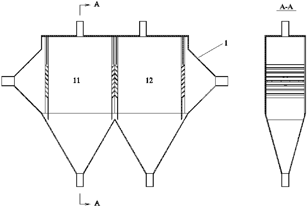
[0086] This embodiment provides a double moving bed reactor 1, and its structure diagram is as follows figure 1 As shown, the double moving bed reactor 1 includes an inlet cavity, a filter bed 11, a catalyst bed 12, and an outlet cavity that are adjacent to each other in sequence, and the inlet cavity, the filter bed 11, the catalyst bed 12, and the outlet cavity are respectively It is separated by the first partition, the second partition and the third partition.

[0087] Wherein, the inlets of the filter bed 11 and the catalyst bed 12 are both located at the top, and the outlets are both located at the bottom.

[0088] The first partition and the third partition are both composed of a louver board, the second partition is composed of two louver boards, the two louver boards are connected together, the distance between the first partition and the second partition The distance between the second partition and the third partition is the same, both are 500 mm.

[00...

Example Embodiment

[0091] Example 2:

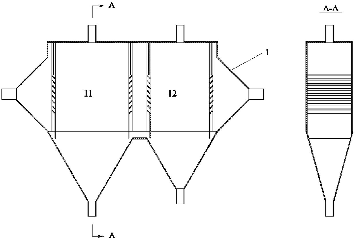
[0092] This embodiment provides a double moving bed reactor 1, and its structure diagram is as follows figure 2 As shown, the double moving bed reactor 1 includes an inlet cavity, a filter bed 11, a catalyst bed 12, and an outlet cavity that are adjacent to each other in sequence, and the inlet cavity, the filter bed 11, the catalyst bed 12, and the outlet cavity are respectively It is separated by the first partition, the second partition and the third partition.

[0093] Wherein, the inlets of the filter bed 11 and the catalyst bed 12 are both located at the top, and the outlets are both located at the bottom.

[0094] The first partition and the third partition are both composed of a louver board, the second partition is composed of two louver boards, the two louver boards are separated by 250mm, and the distance between the first partition and the second partition is 700mm, the distance between the second partition and the third partition is 500mm.

[0095] T...

Example Embodiment

[0097] Example 3:

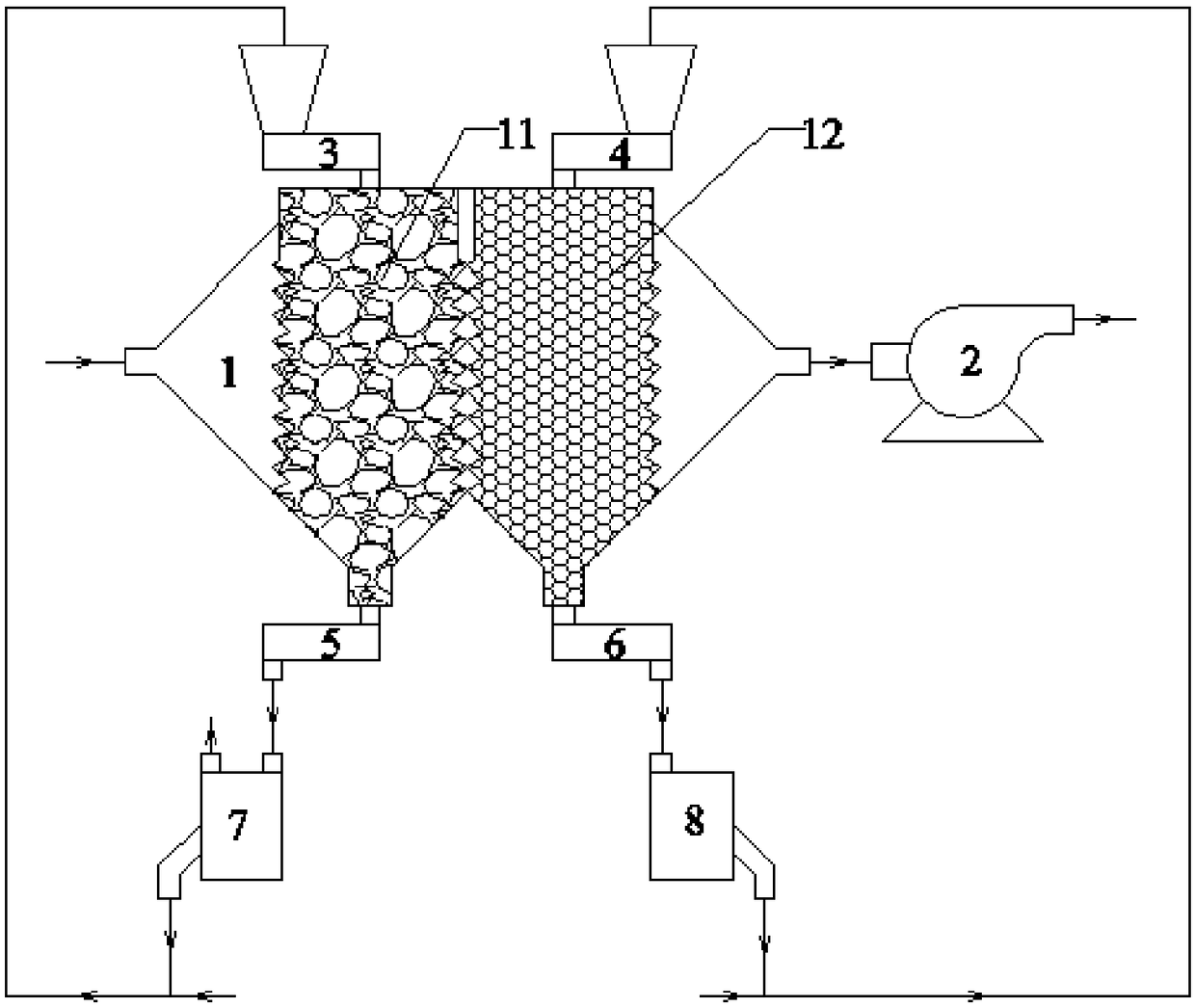
[0098] This embodiment provides an integrated device for flue gas dust removal and denitration. The schematic diagram of the device connection is as follows: image 3 As shown, the device includes the double moving bed reactor 1, a fluidized bed dust removal device 7 and a fluidized bed resurrection device 8.

[0099] Wherein, the structure of the double moving bed reactor 1 refers to Example 1.

[0100] The discharge port of the filter bed 11 in the double moving bed reactor 1 is connected to the feed port of the fluidized bed dust removal device 7, and the discharge port of the fluidized bed dust removal device 7 is connected to the filter The feed port of the material bed 11 is connected, and the feed port of the catalyst bed 12 in the double moving bed reactor 1 is connected to the feed port of the fluidized bed resurrection device 8, and the outlet of the fluidized bed resurrection device 8 The feed port is connected to the feed port of the catalyst bed 12. ...


PUM

PropertyMeasurementUnit
Particle sizeaaaaaaaaaa
Widthaaaaaaaaaa
Heightaaaaaaaaaa

Abstract

The invention provides a double-moving-bed reactor, an application thereof to flue gas dedusting and denitrating integration device and a treatment method. The double-moving-bed reactor comprises a gas inlet cavity, a filter material bed, a catalyst bed and a gas outlet cavity which are adjacent in sequence, and the gas inlet cavity, the filter material bed, the catalyst bed and the gas outlet cavity are separated through a first partition board, a second partition board and a third partition board respectively. According to the device, integrated dedusting and denitrating can be realized, flue gas firstly enters the filter material bed for dedusting, most ultrafine dust in the flue gas is removed, influence of the dust on a catalyst is eliminated, then the flue gas enters the catalyst bedfor removing nitrogen oxides, the two processes are integratedly performed in one reactor, the dedusting and denitrating effects are good, dust removal rate almost reaches 100%, and content of the nitrogen oxides also meets the first level discharge standard. Meanwhile, by means of recycling of a filter material and the catalyst, continuous and stable operation of the dedusting and denitrating process is realized.

Description

Technical field [0001] The invention belongs to the technical field of flue gas purification, and relates to a double moving bed reactor and its use and processing method in an integrated device for flue gas dust removal and denitration. Background technique [0002] At present, there are a large number of glass furnaces, glass frit furnaces, high-temperature tunnel furnaces, and hazardous waste incinerators in China. The combustion temperature of these furnaces generally exceeds 1200℃, and the flue gas produced by combustion contains a large amount of thermal nitrogen oxides. (NO x ), the concentration usually reaches 2000mg / Nm 3 , NO x It will cause harm to the environment, human body, animals and plants, so the flue gas must be denitrified to meet the emission standards. At present, the mainstream technology for flue gas denitrification is selective catalytic reduction (SCR) technology. The principle is to use ammonia as a reducing agent to remove NO in flue gas under conditio...

Claims


Application Information

Patent Timeline
IPC IPC(8): B01D53/86B01D53/56B01D46/00
CPCB01D46/0036B01D53/8631B01D2251/2062B01D2255/20707B01D2255/2073B01D2255/20738B01D2258/0283
Inventor 余剑刘周恩杨娟李长明
Owner INST OF PROCESS ENG CHINESE ACAD OF SCI
Why Eureka
Try Eureka