Photolysis oxidation cracking treatment method for tail gas based on volatile oil and gas purification technology

A cracking treatment, oil and gas technology, applied in chemical instruments and methods, separation methods, dispersed particle separation, etc., can solve the problems of secondary pollution of pollutants, energy waste, low level of intelligent control, etc., achieve energy-saving and efficient treatment, avoid Leakage and ensure zero-emission effect

Pending Publication Date: 2018-06-01
QINGDAO UNIV OF SCI & TECH
View PDF7 Cites 10 Cited by
  • Summary
  • Abstract
  • Description
  • Claims
  • Application Information

AI Technical Summary

Problems solved by technology

However, the intelligent control level of the above-mentioned technical scheme is very low, and the processing power of the ultraviolet equipment cannot be controlled in real time according to the concentration of pollutants, resulting in the waste of energy or the problem that the treatment of pollutants is not up to standard
In addition, the exhaust gas treated by ultraviolet equipment will cause secondary pollution caused by the discharge of pollutants with the flow of water mist in the gas due to the limitations of traditional wet post-treatment equipment (generally using scrubbers).

Method used


Image

  • Photolysis oxidation cracking treatment method for tail gas based on volatile oil and gas purification technology
  • Photolysis oxidation cracking treatment method for tail gas based on volatile oil and gas purification technology
  • Photolysis oxidation cracking treatment method for tail gas based on volatile oil and gas purification technology

Examples


Embodiment Construction

[0033] The specific implementation of the present invention will be further described below in conjunction with the accompanying drawings.

[0034] A tail gas photooxygen cracking treatment method based on volatile oil and gas purification technology, comprising:

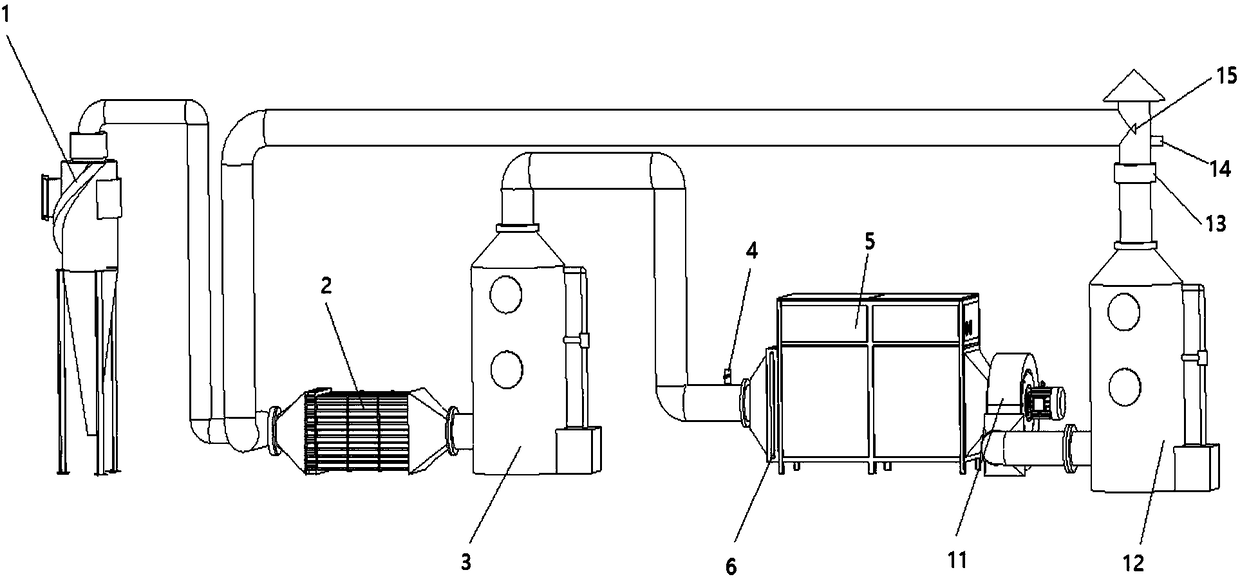
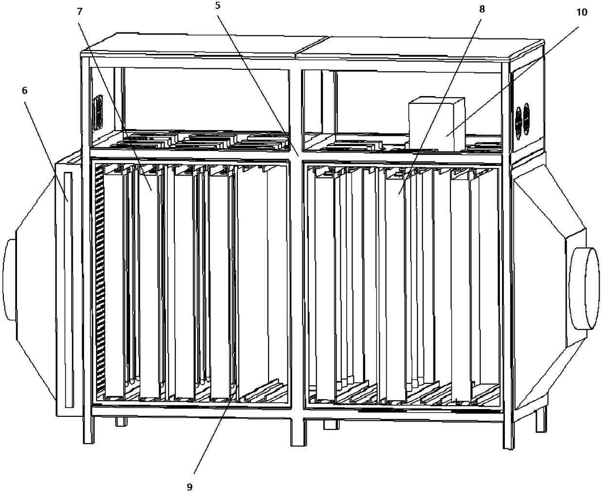
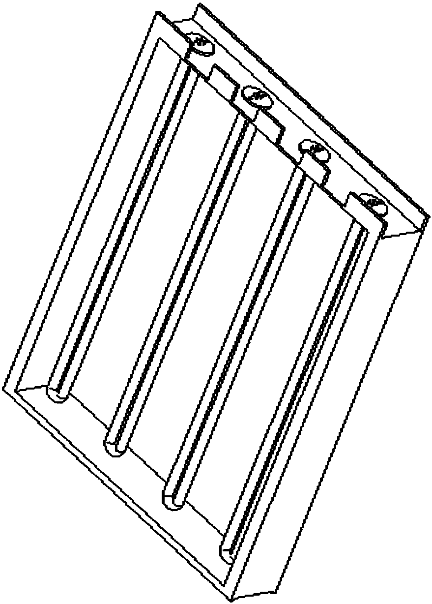
[0035] An exhaust gas treatment device for a rubber factory, including a cyclone defogging and dust-reducing cooler 1, oil and gas purification electric field equipment 2, a front-end spray tower 3, an exhaust gas concentration detection sensor 4, a photo-oxygen cracking cabinet 5, and a dust-proof and wet filter screen 6 , high-energy ultraviolet lamp group module 7, ozone supply module 8, TiO 2 Catalyst net 9, single-chip microcomputer control system, negative pressure induced draft fan 11, dry flue gas comprehensive treatment tank 12, ozone filter screen 13; air inlet and exhaust port of cyclone defogging and dust reduction cooler 1 and factory exhaust port and The oil and gas purification electric field equipme...


PUM


Abstract

The invention discloses a photolysis oxidation cracking treatment method for tail gas based on a volatile oil and gas purification technology. The photolysis oxidation cracking treatment method comprises the following steps: allowing organic waste gas to enter a cyclone defogging and dedusting cooler, allowing macromolecular pollutants to be degraded and decomposed into micro-molecular substancesthrough an oil and gas purifying electric-field device, allowing treated organic waste gas to enter a front-end spraying tower, allowing dust particles to be fixed in a spraying solution, allowing treated organic waste gas to enter a photolysis oxidation cracking cabin through an air pipe, and subjecting waste gas to oxidation treatment; in the oxidation treatment process of the waste gas, allowing a waste gas concentration detection sensor arranged at the inlet position of the photolysis oxidation cracking cabin to detect the concentration of the waste gas in real time and feedback a signal to a single-chip microcomputer control system, and controlling lamp tubes of a high-energy ultraviolet lamp group module and an ozone supply module to regularly and cooperatively open and close; and allowing treated gas to enter a dry flue gas comprehensive treatment tank and an ozone filter screen so as to realize super purified emission after waste gas treatment. The photolysis oxidation crackingtreatment method provided by the invention can realize energy-saving and highly-efficient operation of a whole system, prolongs the service life of a lamp group module, improves the treatment effectof the organic waste gas, avoids the problem of secondary pollution caused by a traditional wet process, and realizes super purified emission.

Description

technical field [0001] The invention relates to the technical field of waste gas treatment, in particular to a tail gas photo-oxygen cracking treatment method based on volatile oil gas purification technology. Background technique [0002] Air pollution is one of the most prominent environmental problems in my country at present. Among them, industrial waste gas is an important source of air pollutants. The most difficult to deal with in industrial waste gas is organic waste gas, which mainly comes from the waste gas emitted during the production process of petrochemical rubber industry. Organic waste gas not only causes direct air pollution, but also participates in complex reactions in the atmosphere to generate secondary pollutants. Become one of the main sources of PM2.5. Therefore, the treatment and purification of organic waste gas need to be solved urgently. [0003] Traditional organic waste gas purification treatment methods mainly include: direct high-temperatur...

Claims


Application Information

Patent Timeline
Patent Type & Authority Applications(China)
IPC IPC(8): B01D50/00B01D53/74B01D53/76B01D53/86B01D53/44B01D53/34
CPCB01D50/00B01D53/346B01D53/74B01D53/76B01D53/8687B01D53/8696
Inventor 汪传生郭磊张鲁琦
Owner QINGDAO UNIV OF SCI & TECH
Why Eureka
Try Eureka