
Fiber transmission channel clock synchronization system and method

A technology of clock synchronization and optical fiber transmission, applied in transmission systems, digital transmission systems, time-division multiplexing systems, etc., can solve problems such as clock inconsistency between channels, and achieve easy engineering implementation, strong confidentiality, and anti-electromagnetic interference strong effect

Active Publication Date: 2019-05-07
ZHEJIANG UNIV +1
View PDF4 Cites 0 Cited by
  • Summary
  • Abstract
  • Description
  • Claims
  • Application Information

AI Technical Summary

Problems solved by technology

[0004] The present invention overcomes the problem of clock inconsistency between channels when the existing distributed measurement and control system uses optical fiber transmission technology to realize large-scale data transmission, and proposes a method that can automatically measure and correct clock inconsistency in optical fiber transmission channels without obtaining the length of optical fiber in advance Fiber Transport Channel clock synchronization system and method

Method used


Image

  • Fiber transmission channel clock synchronization system and method
  • Fiber transmission channel clock synchronization system and method
  • Fiber transmission channel clock synchronization system and method

Examples


Embodiment Construction

[0041] The invention will be further described below in conjunction with the accompanying drawings.

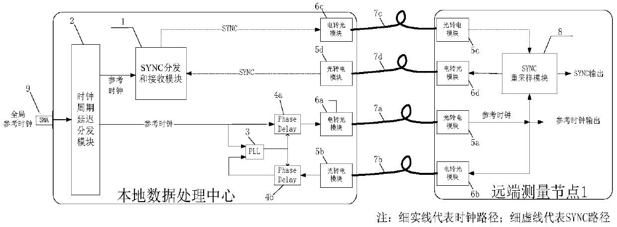
[0042] A common application scenario of the present invention is as figure 1 As shown, the system has multiple discretely distributed remote measurement nodes, which are interconnected with the local data processing center through optical fibers of unequal length. The local data processing center is responsible for transmitting the clock signal and the SYNC signal as a trigger event to all remote measurement nodes. The system requires that the clocks reaching all remote measurement nodes maintain phase consistency, and all SYNC signals can reach all remote measurement nodes at the same time.

[0043] refer to figure 1 and figure 2 , an optical fiber transmission channel clock synchronization system, including: a clock and SYNC processing subsystem for distributing clocks and SYNC signals to different remote nodes, and a signal transmission subsystem for completing optica...


PUM


Abstract

The invention discloses a clock synchronization system for an optical fiber transmission channel. The clock synchronization system comprises a clock and SYNC processing sub-system, a signal transmission sub-system, a clock phase position adjustment sub-system and an SYNC resampling sub-system, wherein the clock and SYNC processing sub-system distributes clocks and SYNC signals for different remotenodes; the signal transmission sub-system is used for finishing optical / electrical and electrical / optical conversion and transmission of the signals; the clock phase position adjustment sub-system isused for adjusting clock phase positions in real time; the SYNC resampling sub-system is used for finishing phase position realignment between the clocks and the SYNCs; the clock and SYNC processingsub-system comprises a clock cycle delayed distribution module, and an SYNC distributing and receiving module; the signal transmission sub-system comprises an electrical-to-optical module, an opticalfiber transmission module and an optical-to-electrical module; and the clock phase position adjustment sub-system comprises a phase-locked loop module and a changeable phase position delay module. Theinvention further comprises a method using the clock synchronization method for the optical fiber transmission channel. According to the clock synchronization method for the optical fiber transmission channel and the method thereof, clock synchronization and sampling synchronization functions between all remote measuring nodes and a local data processing center can be effectively finished, different lengths of optical fibers can be adapted, and the system structure is simple.

Description

technical field [0001] The invention relates to a clock synchronization method and device for multi-channel optical fiber transmission channels. Background technique [0002] As a new type of transmission medium, optical fiber has many obvious advantages compared with traditional copper cables, such as good confidentiality, anti-electromagnetic interference, anti-nuclear radiation, small size, light weight, etc., making optical fiber widely used in civilian and military applications. There are more and more applications in electronic systems. In the field of radar, as an important development direction of phased array radar, digital array radar adopts distributed transmission and reception, the number of sending and receiving nodes is large, and the amount of transmitted data is large. In engineering, optical fiber has been used to realize large-capacity data transmission of digital array radar However, due to the use of equal-length optical fibers, the scope of application...

Claims


Application Information

Patent Timeline
Patent Type & Authority Patents(China)
IPC IPC(8): H04J3/06H04J3/16H04L7/00H04L7/033
CPCH04J3/0638H04J3/1611H04J3/1652H04L7/0075H04L7/033
Inventor 杨李杰徐志伟刘田周文涛
Owner ZHEJIANG UNIV
Learn More