A fuel cell power generation system using liquid hydrogen as fuel

A fuel cell and liquid hydrogen technology, applied in fuel cells, electrochemical generators, circuits, etc., can solve the problem that liquid hydrogen cannot be directly used for power generation by fuel cells, and achieve the effects of light weight, compact structure, and high reliability

Active Publication Date: 2021-02-19
DALIAN INST OF CHEM PHYSICS CHINESE ACAD OF SCI
View PDF9 Cites 2 Cited by
  • Summary
  • Abstract
  • Description
  • Claims
  • Application Information

AI Technical Summary

Problems solved by technology

[0004] However, liquid hydrogen cannot be directly used for fuel cell power generation, it needs to be used after gasification, and the gasification process requires heat from the external environment

Method used


Image

  • A fuel cell power generation system using liquid hydrogen as fuel
  • A fuel cell power generation system using liquid hydrogen as fuel

Examples


Embodiment 1

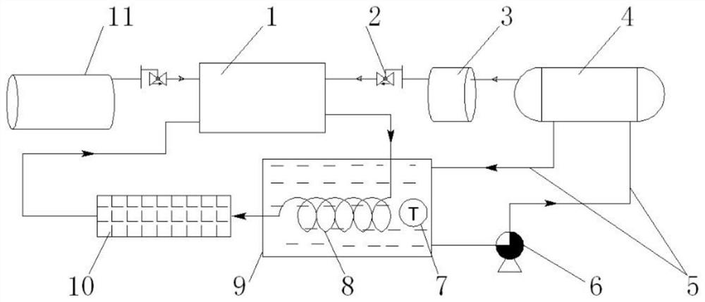
[0019] A schematic flow chart of Embodiment 1 of a fuel cell power generation system using liquid hydrogen as fuel is shown in figure 1 Shown: This process is applicable to the proton exchange membrane fuel cell system of static drainage technology. This embodiment mainly considers the characteristics of the static drainage technology of the fuel cell, separates the thermal management of the fuel cell itself from the thermal management of the liquid hydrogen system, and uses a heat exchanger to realize the excess of thermal energy.

[0020] combine figure 1 , the present invention is composed of a fuel cell module 1, a control valve 2 (such as a solenoid valve), a buffer tank 3, a liquid hydrogen storage tank 4, a circulating water pipeline 5, a circulating water pump 6, a monitoring unit 7, a heat exchanger 8, and a water tank 9, radiator 10, oxygen supply system 11 composition.

[0021] The fuel cell module 1, the heat exchanger 8 and the radiator 10 constitute a thermal m...

Embodiment 2

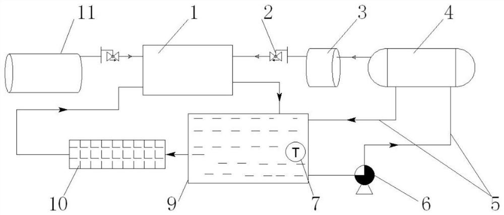
[0026] A schematic flow chart of Embodiment 2 of a fuel cell power generation system using liquid hydrogen as fuel is shown in figure 2 Shown: This process is applicable to the proton exchange membrane fuel cell system with dynamic drainage technology. Considering the own characteristics of the fuel cell dynamic water drainage technology, combining the fuel cell’s own heat management waterway with the liquid hydrogen system’s heat management waterway, the system will omit the heat exchanger 8 in Embodiment 1, and all water circulation lines are at normal pressure Pipeline, the system is simpler. The specific implementation steps are as follows:

[0027] combine figure 2 , the present invention is composed of a fuel cell module 1, a control valve 2 (such as a solenoid valve), a buffer tank 3, a liquid hydrogen storage tank 4, a circulating water pipeline 5, a circulating water pump 6, a monitoring unit 7, a water tank 9, and a radiator 10 , The oxygen supply system 11 is c...


PUM


Abstract

The present invention relates to a fuel cell power generation system using liquid hydrogen as fuel, especially a proton exchange membrane fuel cell power generation system, comprising a proton exchange membrane fuel cell module, a liquid hydrogen storage tank, a buffer tank, a water tank, a heat exchanger, and a control valve , radiator, circulating water pump, circulating water pipeline, monitoring unit and control module. The heat of the fuel cell itself is used to provide a heat source for the liquid hydrogen storage tank to realize the gasification of liquid hydrogen, and then to provide gaseous hydrogen for the fuel cell as fuel. Compared with traditional high-pressure gas cylinder hydrogen storage, metal hydrogen storage and other methods, the present invention has the advantages of large hydrogen storage capacity, light weight, small volume, low working pressure, safety and reliability, fast fuel filling speed, simple fuel filling method, etc. Advantages, especially suitable for fuel cell power generation systems with long endurance requirements.

Description

technical field [0001] The invention relates to a fuel cell power generation system using liquid hydrogen as fuel, in particular to a proton exchange membrane fuel cell power generation system using liquid hydrogen as fuel. Background technique [0002] A fuel cell is different from a battery in the traditional sense. It is a high-efficiency power generation device that converts chemical energy stored in fuel and oxidant into electrical energy through electrochemical reactions. Different from the traditional internal combustion engine, although it needs fuel and oxidant like the internal combustion engine, it does not need to be burned, and can complete the chemical reaction at low temperature to realize the power generation function. There are many types of fuel cells, which can be divided into alkaline fuel cells, proton exchange membrane fuel cells, phosphoric acid fuel cells, molten carbonate fuel cells and solid oxide fuel cells according to different electrolytes. Amo...

Claims


Application Information

Patent Timeline
Patent Type & Authority Patents(China)
IPC IPC(8): H01M8/22H01M8/04029H01M8/04089H01M8/04225
CPCH01M8/04029H01M8/04089H01M8/04268H01M8/22Y02E60/50
Inventor 陶铁男周利邵志刚
Owner DALIAN INST OF CHEM PHYSICS CHINESE ACAD OF SCI
Why Eureka
Try Eureka