
Rotating speed tracking method based on permanent magnet synchronous motor open loop vector

A technology of permanent magnet synchronous motor and motor speed, which is used in the control of generators, vector control systems, motor generator control, etc. Reliability advantages, wide range of estimated speeds, effect of improving reliability

Inactive Publication Date: 2018-06-12
长沙市日业电气有限公司
View PDF4 Cites 15 Cited by
  • Summary
  • Abstract
  • Description
  • Claims
  • Application Information

AI Technical Summary

Problems solved by technology

Although the physical concept of this idea is clear and clear, it is difficult to implement. The scheme has the following problems: 1. There is no DC bus current detection in the general inverter device, and the DC bus current is the smallest and the DC bus capacitance changes within a short period of time. Difficult to judge; 2. If there is a large gap between the current searched stator magnetic field frequency and the actual motor speed, especially when the stator magnetic field frequency is in the opposite direction to the motor's actual speed, the search time of the speed search device will be longer

Method used

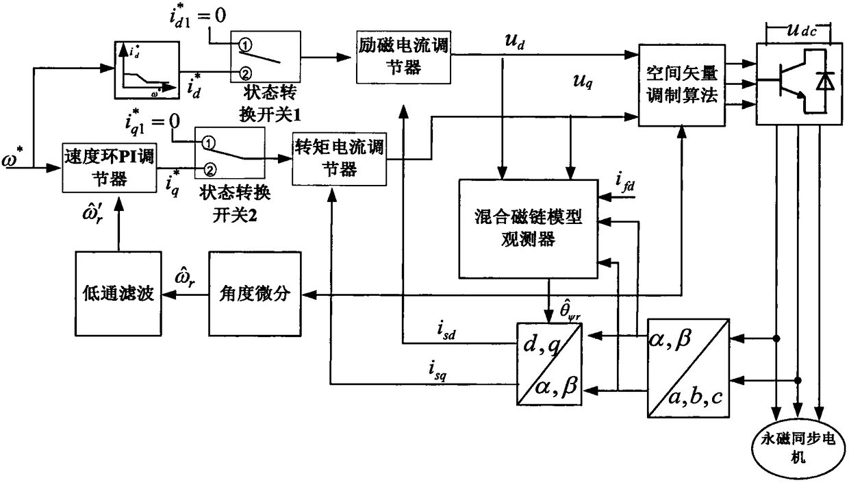

Image

  • Rotating speed tracking method based on permanent magnet synchronous motor open loop vector
  • Rotating speed tracking method based on permanent magnet synchronous motor open loop vector
  • Rotating speed tracking method based on permanent magnet synchronous motor open loop vector

Examples


Embodiment Construction

[0042]The present invention will be further described below in conjunction with the accompanying drawings and specific embodiments.

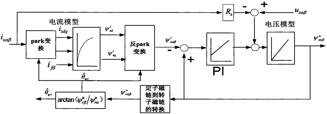
[0043] figure 1 It is a structural block diagram of an embodiment of the speed tracking based on the open-loop vector of the permanent magnet synchronous motor in the present invention, such as figure 1 As shown, the speed tracking control system of the open-loop vector of the permanent magnet synchronous motor of the present invention includes: stator current Clarke and Parker coordinate transformation module, torque current loop regulator, excitation current loop regulator, speed loop PI regulator, state conversion switch 1 and 2, speed excitation current relationship module, hybrid flux linkage model observer, angle differential module, low-pass filter module, and space vector algorithm module. When the system is running normally, the speed closed-loop control is adopted, and the state conversion module connects the two terminals with the to...


PUM


Abstract

The invention discloses a rotating speed tracking method based on a permanent magnet synchronous motor open loop vector. The method comprises the following steps of 1, using a mixing model flux linkage observer to estimate a current motor rotor flux linkage angle, then carrying out differential and estimating a current motor rotating speed; 2, carrying out coordinate conversion on a stator currentvector and acquiring an excitation current id and a torque current iq; 3, taking the id and zero as input, carrying out operation by an excitation current regulator and acquiring an excitation voltage ud; taking the iq and the zero as the input, through a torque current regulator, acquiring a torque voltage uq; 4, carrying out vector synthesis on the ud and the uq, carrying out space vector modulation wave calculation, and comparing with a triangular wave to generate a driving control signal so as to drive a permanent magnet synchronous motor; and 5, repeating the steps1, 2, 3 and 4 till thattwo current vectors are stabilized near the zero and maintain for a short time period, considering the rotating speed estimated at this moment to be a current motor rotation speed, taking the currentrotation speed as a start rotation speed and smoothly switching to synchronization motor speed control.

Description

technical field [0001] The invention belongs to the technical field of speed regulation of permanent magnet synchronous motors, in particular to a speed tracking method based on open-loop vectors of permanent magnet synchronous motors. Background technique [0002] In high-performance permanent magnet co-motor vector control systems, closed-loop speed control is usually used. The speed is generally obtained by the encoder and estimated according to the mathematical model. However, because the encoder affects the simplicity and reliability of the permanent magnet synchronous motor speed control system in terms of installation, maintenance, and cost, people have proposed an open-loop vector speed closed-loop Control plan. The core problem is the estimation of rotor speed information. There are many algorithms for estimating the speed of permanent magnet synchronous motors. For example, direct calculation, observer, self-adaptation, artificial intelligence and other means are...

Claims


Application Information

Patent Timeline
IPC IPC(8): H02P21/13H02P21/18H02P21/22H02P21/34H02P6/182
CPCH02P6/182H02P21/13
Inventor 匡江传曾智波
Owner 长沙市日业电气有限公司
Learn More