
Optical fiber array phase array deflection transmission system based on SPGD algorithm

A launch system and optical fiber array technology, which is applied in the field of photoelectric detection, can solve the problems of inability to phase control the operating temperature of the launch system and feedback adjustment of laser power, the inability to meet the needs of long-distance detection, and the inability to realize deflection scanning, etc.

Active Publication Date: 2018-06-22
BEIJING INSTITUTE OF TECHNOLOGYGY
View PDF12 Cites 24 Cited by
  • Summary
  • Abstract
  • Description
  • Claims
  • Application Information

AI Technical Summary

Problems solved by technology

However, the current fiber array coherent combination technology based on the SPGD algorithm can only realize the coherent combination of several pulsed beams (for example, the document "Pulsed Laser Coherent Combination Technology Based on Active Phase Control" realizes the coherent combination of two pulsed lasers), the combined power Too low, it is not possible to feedback and adjust the operating temperature and laser power of the phased emission system, so it cannot meet the multi-functional and adjustable long-distance detection requirements
Moreover, the existing SPGD algorithm-based optical fiber array coherent combination technology cannot realize deflection scanning at a specific angle, so it is impossible to detect suspicious targets in real time with high sensitivity, which makes the application of optical fiber phased array laser radar in many fields severely handicapped

Method used


Image

  • Optical fiber array phase array deflection transmission system based on SPGD algorithm
  • Optical fiber array phase array deflection transmission system based on SPGD algorithm
  • Optical fiber array phase array deflection transmission system based on SPGD algorithm

Examples


Embodiment 1

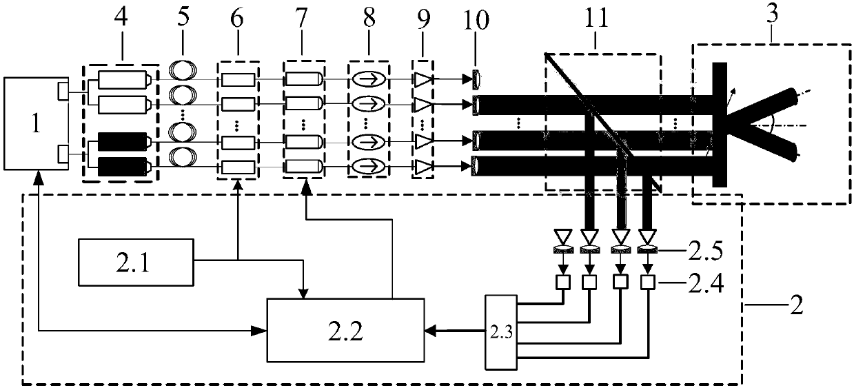
[0052] A kind of optical fiber array phased array deflection launch system based on SPGD algorithm of the present embodiment, such as figure 1 As shown, the specific implementation steps are as follows:

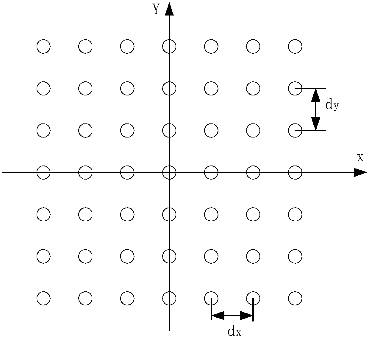
[0053] Step 1. Arrange 49 optical fibers in a two-dimensional square. The specific arrangement is as follows figure 2 As shown, there are 7 pieces arranged in the direction of the x-axis and 7 pieces arranged in the direction of the y-axis, and the spacing of the phase-controlled units is set to d=d x = d y = 4.1um. 2.1 reference phase information to the RF reference oscillator according to scanning detection requirements Then let the drive and temperature control circuit system 1 start to work, provide feedback and precise and stable drive for the continuous fiber laser 4, make the continuous fiber laser 4 always work at a constant temperature and high power state, and let 49 continuous fiber lasers 4 emit 49 continuous lasers , to prepare for the subsequent coherent c...

Embodiment 2

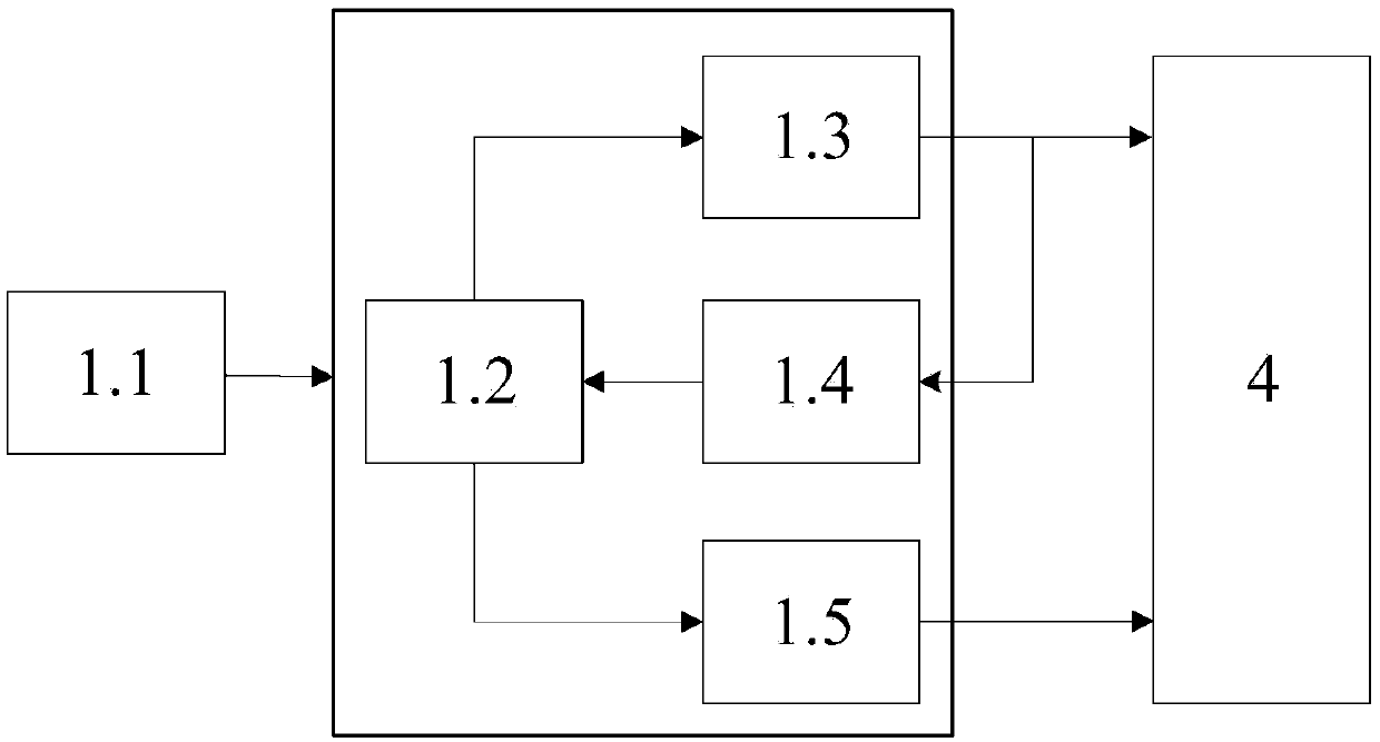
[0066] In this embodiment, an optical waveguide phased array control beam deflection principle of an optical fiber array phased array deflection transmission system based on the SPGD algorithm is as follows: image 3 As shown, the specific process is as follows:

[0067] In this embodiment, 49 optical fibers are arranged in a 7×7 square, with 7 optical fibers in the x direction and 7 optical fibers in the y direction. The phase number corresponding to each optical fiber is (n=1-49, x=1-7, y=1-7, n=xy). If a specific two-dimensional scan angle θ xy =(θ x , θ y ) = (15°, 15°) (wherein, θ x =15° means that the coherently combined beam is deflected by an angle of 15° along the x direction, θ y =15° means that the beam after coherent combination is deflected by 15° along the y direction), when the Gaussian wave with good coherence is incident on the 49-layer optical phased array, if there is no additional phase, the complex amplitude distribution of the output light field is:...

Embodiment 3

[0083] In this embodiment, an optical fiber array phased array deflection transmission system based on the SPGD algorithm realizes active phase control for 49 beams. The specific process of implementing the phase control of the 49 beams based on the SPGD algorithm is as follows:

[0084] Define the evaluation function J=J(μ 1 ,μ 2 ,…,μ 49 ) is the phase control signal (μ 1 ,μ 2 ,…,μ 49 )The function. The influence of the evaluation function on each beam control signal can be expressed as:

[0085]

[0086] In the formula, J′ j Indicates the gradient of the evaluation function relative to the control signal of the jth light beam after the mth adjustment; γ is the corresponding coefficient.

[0087] Use δu j Indicates the change amount of the jth light beam control signal, then, the change amount of the evaluation function is:

[0088] δJ=J(u 1 , u 2 ,...,u j +δu j ,...,u 49 )-J(u 1 , u 2 ,...,u j ,...,u 49 ) (12)

[0089] For the SPGD algorithm, the incremen...


PUM


Abstract

The invention relates to an optical fiber array phase array deflection transmission system based on SPGD algorithm, belonging to the technical field of photoelectric detection. The system includes a driving and temperature control circuitry, an optical wave phase control system based on SPGD algorithm, a continuous fiber laser, an optical fiber, an electro-optic modulator, a phase modulator, an optical isolator, a continuous fiber amplifier, a collimating beam expander and a sampler. In the invention, the power of N continuous optical fiber lasers can be amplified by using a feedback fine stable driving and temperature control circuit, the N ways of the synthesized light beams can be increased without limit according to the requirement of detection power, At the same time, by using SPGD algorithm , the closed-loop feedback regulation and phase real-time compensation of the phase of the power amplified pulse light changes of N-way can be realized, It can realize the phase locking of theN-way pulsed beam while meeting the beam coherent synthetic deflection under a certain angle. And it can solve the problem of great inertia of traditional mechanical scanning, low sensitivity, closedetection distance and its traditional SPGD method not realizing the deflection of scanning beam.

Description

technical field [0001] The invention relates to an optical fiber array phased array deflection emission system based on SPGD algorithm, which belongs to the field of photoelectric detection technology. Background technique [0002] Compared with the traditional mechanical scanning radar transmission system, the optical fiber phased array lidar transmission system is widely used in many fields such as military reconnaissance, multi-target tracking, and terrain mapping because of its advantages such as small inertia, fast scanning speed, and high sensitivity. However, these detection fields have the characteristics of complex ground conditions and long distances, and the existing optical fiber phased array lidar cannot meet the long-distance and high-sensitivity detection requirements due to low transmission power and poor sensitivity. The high-power laser output of phased array radar has become a major problem in the field of photoelectric detection today. [0003] At presen...

Claims


Application Information

Patent Timeline
IPC IPC(8): G01S7/484
CPCG01S7/484
Inventor 曹杰郝群张佳利李毅东闫雷孟令通
Owner BEIJING INSTITUTE OF TECHNOLOGYGY
Learn More