
Transient voltage suppressor and manufacturing method thereof

A technology of transient voltage suppression and manufacturing method, applied in the direction of electric solid devices, circuits, electrical components, etc., can solve the problems of large size of bidirectional transient voltage suppressor, high cost of chip patch, unsuitable for packaging, etc. Reduce the difficulty of production, high chip area utilization, and the effect of chip size compression

Active Publication Date: 2018-06-22
BEIJING YANDONG MICROELECTRONICS
View PDF6 Cites 2 Cited by
  • Summary
  • Abstract
  • Description
  • Claims
  • Application Information

AI Technical Summary

Problems solved by technology

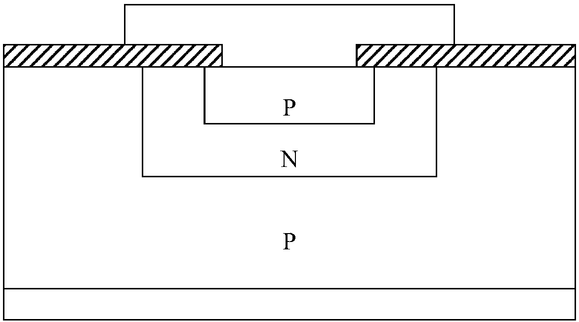
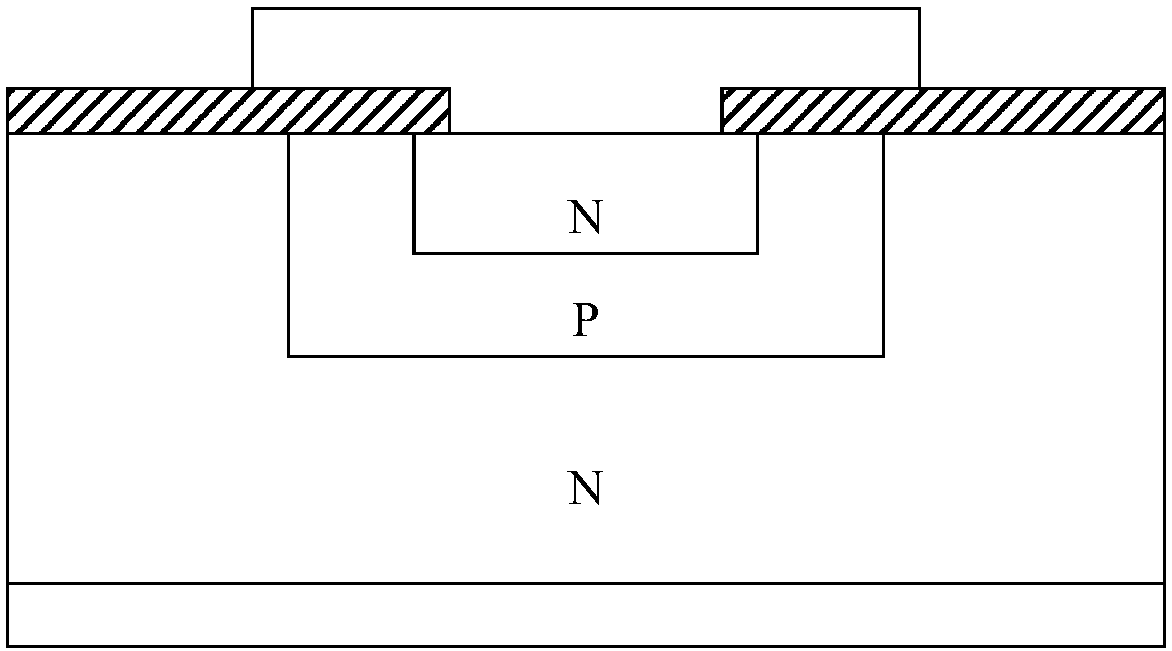
like Figure 2c As shown, since two chips need to be placed on the base island in this bidirectional transient voltage suppressor, it is easy to cause the probability of packaging defects to increase, so that the cost of chip placement is relatively high; during the packaging process, the two A metal wire needs to be punched at each channel end, which also increases the cost; at the same time, because the integrated package of multiple chips requires a large space, the size of the entire bidirectional transient voltage suppressor is large, which is not suitable for smaller packages.

Method used


Image

  • Transient voltage suppressor and manufacturing method thereof
  • Transient voltage suppressor and manufacturing method thereof
  • Transient voltage suppressor and manufacturing method thereof

Examples


Embodiment Construction

[0044] The present invention is described below based on examples, but the present invention is not limited to these examples. In the following detailed description of the embodiments of the present invention, some specific details are described in detail, and those skilled in the art can fully understand the present invention without the description of these details. In order to avoid obscuring the essence of the present invention, well-known methods, procedures, and flow charts are not described in detail.

[0045] In the various figures, identical elements are indicated with similar reference numerals. For the sake of clarity, various parts in the drawings have not been drawn to scale. Also, some well-known parts may not be shown in the drawings. The flowcharts and block diagrams in the accompanying drawings illustrate the possible system framework, functions and operations of the systems, methods, and devices of the embodiments of the present invention, and the blocks an...


PUM


Abstract

The invention discloses a transient voltage suppressor and a manufacturing method thereof. The transient voltage suppressor includes: a semiconductor substrate; an epitaxial layer arranged on a firstsurface of the semiconductor substrate; a first buried layer extending from the first surface of the semiconductor substrate to the interior of the semiconductor substrate, wherein the first buried layer and the semiconductor substrate from a PN junction; a second buried layer, wherein a part of the second buried layer and a part of the first buried layer from a first transient voltage suppressingtube; a plurality of isolation areas extending from a surface of the epitaxial layer to the interior of the first buried layer or the second buried layer; a plurality of well regions extending from the surface of the epitaxial layer to the interior of the epitaxial layer, wherein at least one of the plurality of well regions contacts the corresponding isolation area so as to form a second transient voltage suppressing tube, and at least part of the first buried layer and the semiconductor substrate are electrically connected so as to allow short out of the PN junction. The transient voltage suppressor has a bidirectional transient voltage suppressing function, is low in capacitance, is small in size, is easy to manufacture, and can lead electrodes from a front surface and a back surface.

Description

technical field [0001] The present invention relates to the technical field of semiconductor microelectronics, and more specifically, to a transient voltage suppressor and a manufacturing method thereof. Background technique [0002] Transient Voltage Suppressor (TVS) is a high-efficiency circuit protection device that is commonly used at present. Its appearance is the same as that of ordinary diodes, but its special structure and process design enable it to absorb waves up to several thousand watts. surge power. The working mechanism of the transient voltage suppressor is: under reverse application conditions, when the transient voltage suppressor is subjected to a high-energy large pulse, its working impedance will quickly drop to an extremely low conduction value, thereby allowing large current flow through, while clamping the voltage at a predetermined level, the general response time is only 10 -12 seconds, so it can effectively protect the precision components in the...

Claims


Application Information

Patent Timeline
Patent Type & Authority Applications(China)
IPC IPC(8): H01L27/02
CPCH01L27/0255H01L27/0292H01L27/0296
Inventor 周源郭艳华李明宇张欣慰
Owner BEIJING YANDONG MICROELECTRONICS
Learn More