
Ultrasonic vibrating aided welding test device

A technology for auxiliary welding and testing equipment, applied in welding equipment, non-electric welding equipment, metal processing equipment, etc., can solve the problems of unfixed impact time and distance, strict requirements on the shape of the welded parts, and difficulty in accurately controlling energy, etc. , to achieve the effect of reducing welding defects, uniform grain size, and accelerating escape

Pending Publication Date: 2018-06-29
ARMOR ACADEMY OF CHINESE PEOPLES LIBERATION ARMY
View PDF0 Cites 8 Cited by
  • Summary
  • Abstract
  • Description
  • Claims
  • Application Information

AI Technical Summary

Problems solved by technology

Due to the inertia of the up and down movement of the hammer head, the impact time and distance of the piston of the air hammer are not fixed, so it is difficult to accurately control the energy of each hammering. At the same time, the vibration of the hammer head is large, and an additional guide mechanism is required.
Rolling with welding and impact rolling with welding have huge equipment, mainly relying on the bearings of the rolling wheel to bear the rolling pressure. The size of the rolling wheel is large, the accessibility is poor, and it is easy to interfere with the welding torch to cause arcing. At present, the main It is used for tailor welding seam of long straight flat plate, longitudinal seam and circular seam welding of larger cylinder, and has strict requirements on the shape of welded parts, which is difficult to meet the actual production demand
Severe segregation may be caused by chilling with welding, and the transverse shrinkage of the weld will increase
In addition, the cooling medium can also contaminate the weld seam

Method used


Image

  • Ultrasonic vibrating aided welding test device
  • Ultrasonic vibrating aided welding test device
  • Ultrasonic vibrating aided welding test device

Examples


Embodiment

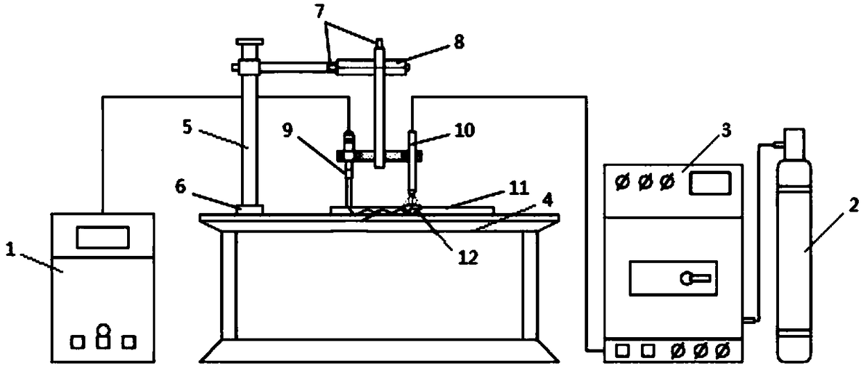
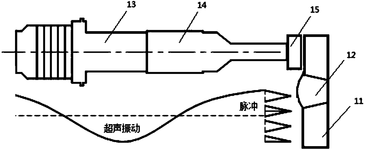
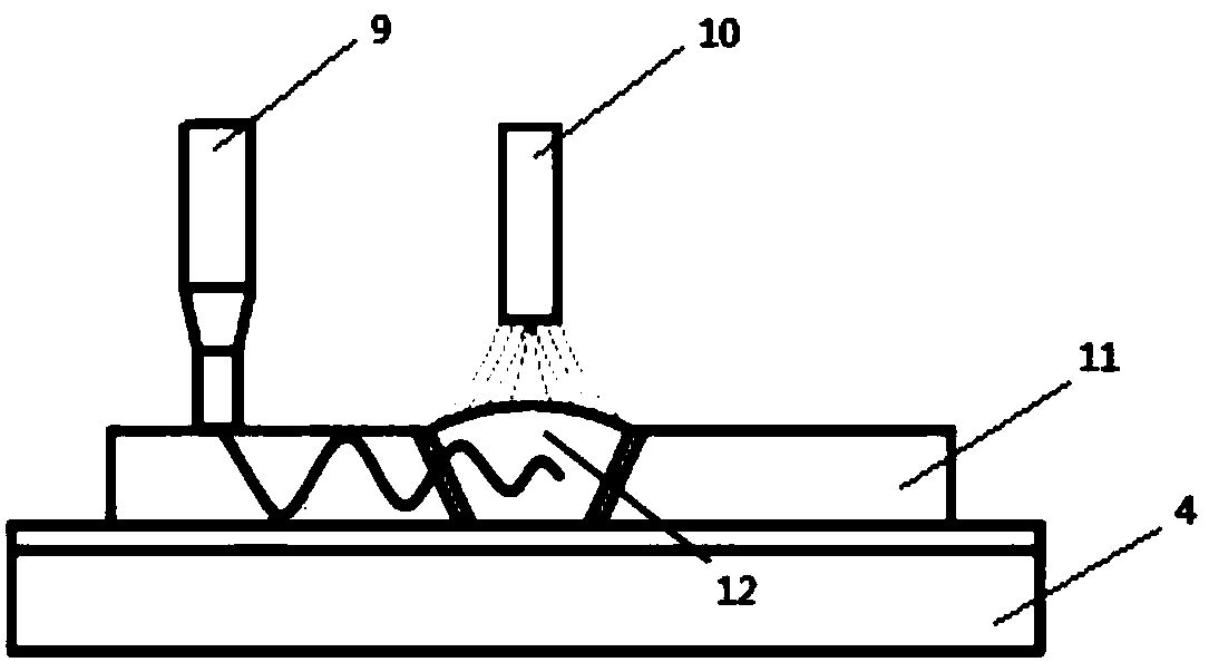
[0021] Example: such as Figure 1-3 As shown, the present invention provides a kind of ultrasonic vibration assisted welding test device, comprises sonotrode 1, gas cylinder 2, welding power source 3 and the transducer 13 that is connected with sonotrode 1; 4. The workpiece 11 on the surface, the ultrasonic generator 1 and the welding power supply 3 are respectively connected with a vibrating gun 9 and a welding torch 10, the welding torch 10 is located above the molten pool 12 on the surface of the workpiece 11, and the vibrating gun 9 and the welding torch 10 are fixed by connecting rods On the ball screw 8, the vibrating gun 9 and the welding torch 10 are hoisted side by side on the upper end of the workpiece 11; the vibrating gun 9 includes a transducer 13, a horn 14 and a vibrating head 15; the ultrasonic generator 1 is connected to the transducer 13, One end of the transducer 13 is connected to the horn 14 , and the other end of the horn 14 is installed with a vibrating ...


PUM


Abstract

The invention discloses an ultrasonic vibrating aided welding test device. The device mainly comprises an ultrasonic vibration processing device, a supporting and adjusting mechanism, a welding platform, etc. According to the device, a welding part in normal welding is subjected to regular ultrasonic vibration processing through a vibrating gun, and a welding pool is vibrated, thus the welding seam metal crystallizing process is changed, and the uniformity of the structure performance of a welding joint can be improved, and as a result, the welding quality is improved; alternative pressure isapplied to the metal in crystallizing in the welding pool by the ultrasonic vibration, thus high impact wave is generated for cutting off the growing crystal grains with sufficient energy, and as a result, the quantity of crystal nucleuses can be increased, the crystal form can be changed, and the condensed welding seam metal crystal grains can be refined; and meanwhile, metal in the welding poolis stirred at high speed, thus gas and impurities can quickly float, and the components are uniform, and as a result, the condensing state of the metal in the welding pool can be improved, and the comprehensive mechanical properties of the welding seam metal can be improved.

Description

technical field [0001] The invention belongs to the technical field of welding equipment and technology, and relates to a test device for suppressing welding hot cracks of materials such as high-strength aluminum alloy, alloy steel, and low-carbon steel, and improving the mechanical properties of its welded joints. Background technique [0002] Hot cracks are the most common defects in welding production. From commonly used low carbon steel, alloy steel to various alloys, hot cracks may occur during welding, especially some high-strength aluminum alloys commonly used in aviation and aerospace fields. Hot tear sensitivity is great. At present, it is difficult to completely eliminate large welding defects such as welding hot cracks, pores, lack of fusion, and incomplete penetration through post-welding treatment, and the existence and development of these defects will affect the performance of the weld metal and become failures. risk of accidents. [0003] The occurrence of ...

Claims


Application Information

Patent Timeline
IPC IPC(8): B23K20/10B23K20/26
CPCB23K20/10B23K20/26
Inventor 李占明孙晓峰何嘉武邱骥宋巍杜晓坤郝松松史玉鹏干杰
Owner ARMOR ACADEMY OF CHINESE PEOPLES LIBERATION ARMY
Learn More