Coal gasification method and coal gasification system

A technology for coal gasification and crude gas, applied in the field of coal gasification, can solve the problems of easy short circuit of gas, insufficient coal gasification reaction, uneven distribution of gas flow, etc.

Active Publication Date: 2018-06-29
ENN SCI & TECH DEV
View PDF8 Cites 5 Cited by
  • Summary
  • Abstract
  • Description
  • Claims
  • Application Information

AI Technical Summary

Problems solved by technology

[0003] In the prior art, fluidized bed gasification furnaces are usually used for coal gasification, wherein the addition of catalysts can catalyze the occurrence of methanation reactions of carbon water, water gas shift, carbon monoxide and hydrogen, but in fluidized bed gasification furnaces , the occurrence of methanation reaction requires stable temperature and long gas-solid contact time, which requires controlling the higher density bed height and lower gas velocity of the fluidized bed gasifier, and the flow The fluidized bed gasification furnace has defects such as poor fluidization quality, easy short circuit of gas, and easy occurrence of throttling in the furnace. The low gas velocity of the gasification agent at the bottom exacerbates the uneven distribution of the air flow, further deteriorating the flow field, resulting in gas Insufficient chemical reaction, high local temperature and easy slagging
In addition, the occurrence of methanation reaction also requires a certain amount of CO and H 2 In the prior art, the methane yield is increased by returning the synthesis gas to the furnace. However, the return of the synthesis gas to the furnace inhibits the occurrence of the carbon-water reaction in the furnace, resulting in a low carbon conversion rate, which limits the methanation reaction to a certain extent.

Method used


Image

  • Coal gasification method and coal gasification system
  • Coal gasification method and coal gasification system
  • Coal gasification method and coal gasification system

Examples


Embodiment Construction

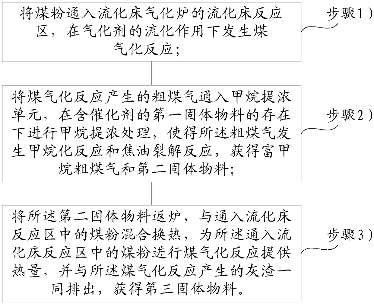
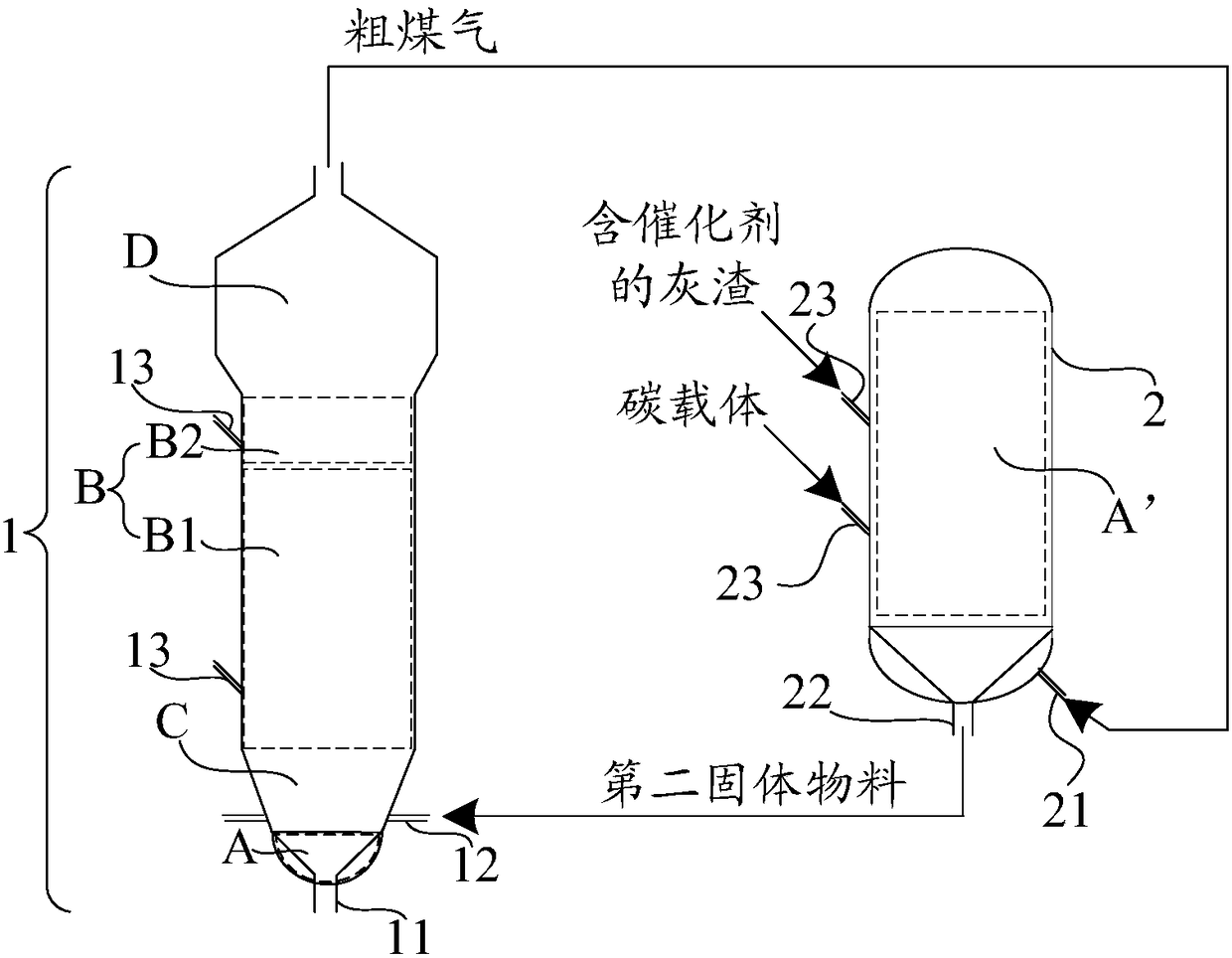
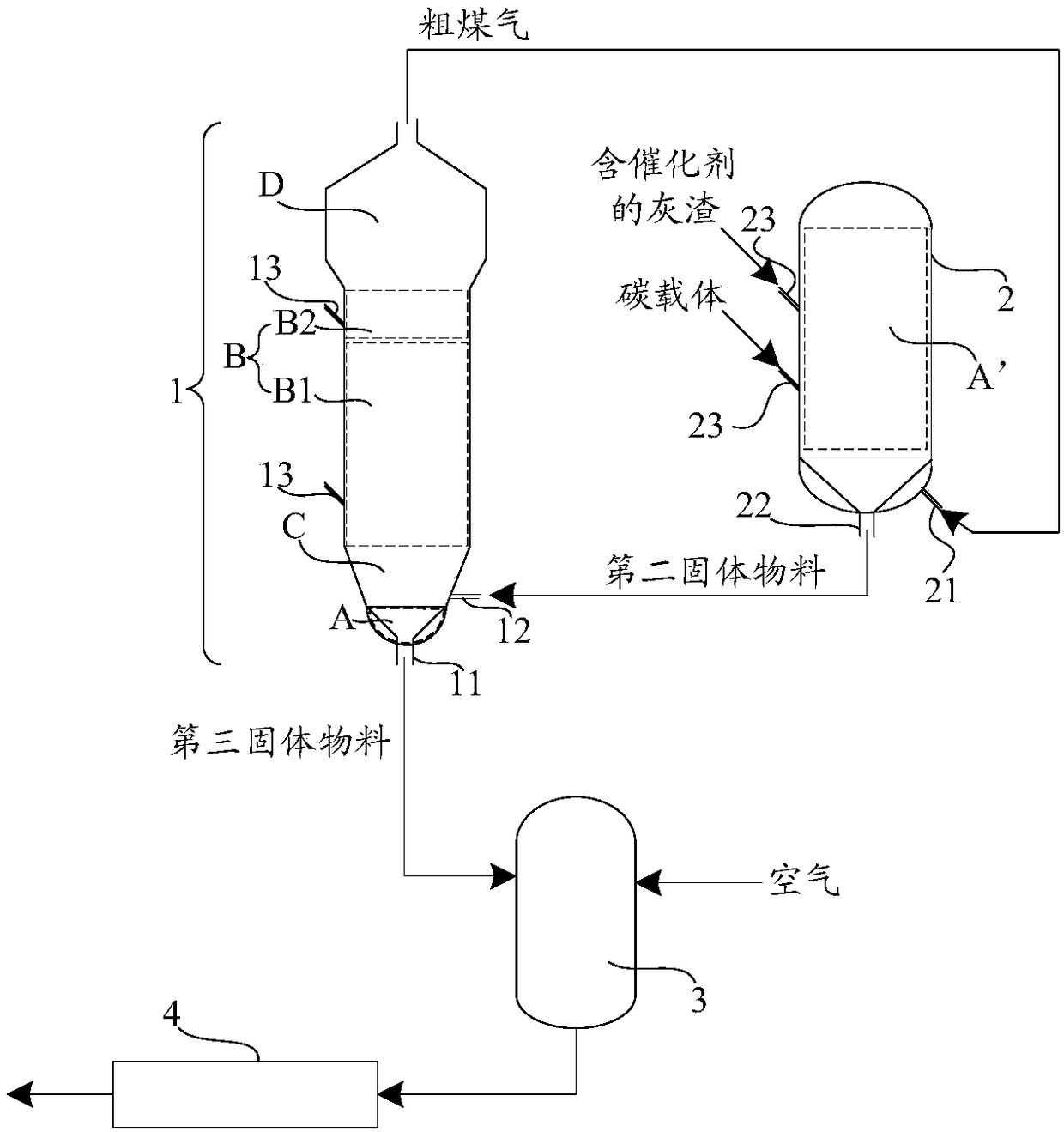
[0044] The following will clearly and completely describe the technical solutions in the embodiments of the present invention with reference to the accompanying drawings in the embodiments of the present invention. Obviously, the described embodiments are only some, not all, embodiments of the present invention. Based on the embodiments of the present invention, all other embodiments obtained by persons of ordinary skill in the art without making creative efforts belong to the protection scope of the present invention.

[0045] In describing the present invention, it is to be understood that the terms "center", "upper", "lower", "front", "rear", "left", "right", "vertical", "horizontal", The orientations or positional relationships indicated by "top", "bottom", "inner", "outer", etc. are based on the orientations or positional relationships shown in the drawings, and are only for the convenience of describing the present invention and simplifying the description, rather than indi...


PUM

PropertyMeasurementUnit
particle diameteraaaaaaaaaa

Abstract

The invention relates to the technical field of coal gasification, and especially to a coal gasification method and a coal gasification system. The method and the system can improve the fluidization quality in a gasifier, improve the flow field in the gasifier, avoid slagging in the gasifier and improve the running stability and the methane yield of the gasifier. The coal gasification method comprises the following steps: introducing coal powder into a fluidized bed reaction zone, and performing a coal gasification reaction under the fluidization action of a gasifying agent; introducing raw gas generated by the coal gasification reaction into a methane concentration unit, and performing methane concentration treatment in the presence of a first solid material containing a catalyst to makethe raw gas undergo a methanation reaction and a tar cracking reaction in order to obtain methane-rich raw gas and second solid material; and returning the second solid material into the gasifier, performing mixing and heat-exchanging on the second solid material and the coal dust in the fluidized bed reaction zone to provide heat for the coal gasification reaction of the coal dusts in the fluidized bed reaction zone, and discharging ash and slag generated in the coal gasification reaction to obtain a third solid material.

Description

technical field [0001] The invention relates to the technical field of coal gasification, in particular to a coal gasification method and system. Background technique [0002] With the rapid economic development and increasingly stringent environmental regulations, the demand for natural gas, a clean energy, is growing explosively. Catalytic gasification technology is an important way to use coal cleanly and efficiently, and it is one of the most effective ways to produce natural gas from coal. Using catalytic gasification technology, coal is gasified with a gasification agent at a relatively low temperature under the catalytic action of a catalyst to generate high-concentration methane. [0003] In the prior art, fluidized bed gasification furnaces are usually used for coal gasification, wherein the addition of catalysts can catalyze the occurrence of methanation reactions of carbon water, water gas shift, carbon monoxide and hydrogen, but in fluidized bed gasification fur...

Claims


Application Information

Patent Timeline
Patent Type & Authority Applications(China)
IPC IPC(8): C10J3/54C10J3/84
CPCC10J3/54C10J3/84C10J2300/093C10J2300/0976C10J2300/1603C10J2300/1625C10J2300/1662C10J2300/1807Y02P20/52
Inventor 李克忠毛燕东刘雷
Owner ENN SCI & TECH DEV
Why Eureka
Try Eureka