Combined storage cabinet and control method thereof
A control method and combined technology, applied in loading/unloading, conveyor, transportation and packaging, etc., can solve problems such as centralized control and maintenance of unfavorable equipment, large-scale production, operation and maintenance costs, difficulties in fabricating vehicle production and installation, etc. , to achieve the effect of reducing the workload of operation and maintenance personnel, reducing production and maintenance costs, and simple and reliable control
- Summary
- Abstract
- Description
- Claims
- Application Information
AI Technical Summary
Problems solved by technology
Method used
Image
Examples
Embodiment 1
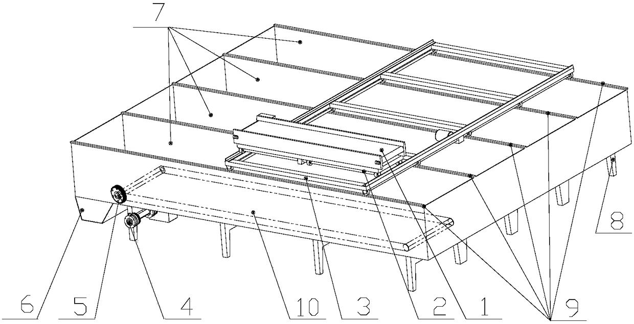
[0038] Such as figure 1 and figure 2 As shown, the embodiment provides a combined storage cabinet for classified storage of tobacco materials, its structure is as follows figure 1 As shown, it includes: a conveying mechanism 1, a longitudinal traveling mechanism 3, a transverse traveling mechanism 2, a longitudinal guide rail 9, a bottom belt drive mechanism 4, a bottom belt sprocket 5, a discharge device 6 and a storage bin 7.
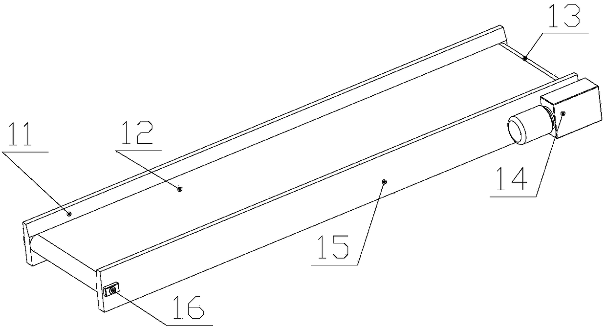
[0039] Specifically, the conveying mechanism 1 includes: a left support 11, a conveyor belt 12, a driving roller 13, a driving unit 14, a right support 15, and a driven roller 16; On the conveyor belt 12, the driving unit 14 drives the conveyor belt 12 to run, and the material is transported by the conveyor belt 12 to the storage bin 7 below the conveyor mechanism 1, wherein the length of the conveyor mechanism 1 is less than half of the length of the storage bin 7, and the conveyor belt 12 It can run in two directions. The driving unit 14 controls...
Embodiment 2
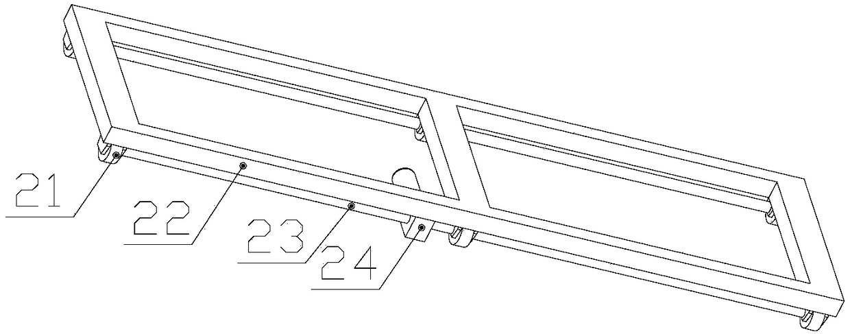
[0041] Such as figure 1 and image 3 As shown, the embodiment provides a lateral travel mechanism 2, specifically, the lateral travel mechanism 2 includes: lateral travel wheels 21, lateral frame 22, lateral travel drive shaft 23, lateral travel drive unit 24; The frame 22 below is provided with a plurality of lateral travel wheels 21, and the lateral travel drive unit 24 drives the lateral travel drive shaft 23, drives the lateral travel wheels 21 to roll, and performs lateral reciprocating motion on the lateral guide rail 32, which can be controlled by the position sensing device on the guide rail. Stop at any position, and when the designated position is reached, the conveying mechanism 1 above the transverse traveling mechanism 2 starts, and the material is transported to the storage bin 7 below. The transverse running mechanism 2 cooperates with the conveying mechanism 1 to effectively classify different types of materials and put them into different storage bins, preven...
Embodiment 3
[0043] Such as figure 1 and Figure 4 As shown, the embodiment provides a longitudinal traveling mechanism 3, specifically, the longitudinal traveling mechanism 3 includes: a longitudinal traveling drive unit 31, a transverse guide rail 32, a longitudinal traveling drive shaft 33, a longitudinal frame 34, and a longitudinal traveling wheel 35, A plurality of longitudinal travel wheels 35 are arranged below the longitudinal frame 34 at both ends, and the longitudinal travel drive unit 31 drives the longitudinal travel drive shaft 33, drives the longitudinal travel wheels 35 to roll, and performs longitudinal reciprocating motion on the longitudinal guide rail 9, controlled by a position sensing device It can stop at any position of the guide rail, and when the designated position is reached, the upper transverse traveling mechanism 2 starts along the transverse guide rail 32 arranged on the top of the longitudinal traveling mechanism 3 to determine the transverse position for d...
PUM
 Abstract
Description
Claims
Application Information
 - R&D
- Intellectual Property
- Life Sciences
- Materials
- Tech Scout
- Unparalleled Data Quality
- Higher Quality Content
- 60% Fewer Hallucinations
Browse by: Latest US Patents, China's latest patents, Technical Efficacy Thesaurus, Application Domain, Technology Topic, Popular Technical Reports.
© 2025 PatSnap. All rights reserved.Legal|Privacy policy|Modern Slavery Act Transparency Statement|Sitemap|About US| Contact US: help@patsnap.com


