oscillator system

An oscillator and operational amplifier technology, applied in the field of integrated circuit design, can solve the problems of high power consumption and the output frequency is greatly affected by temperature, and achieve the effects of reducing power consumption, improving temperature characteristics, and improving stability

Active Publication Date: 2021-06-18
INST OF MICROELECTRONICS CHINESE ACAD OF SCI
View PDF5 Cites 1 Cited by
  • Summary
  • Abstract
  • Description
  • Claims
  • Application Information

AI Technical Summary

Problems solved by technology

[0004] The above RC oscillator uses a comparator structure, so it consumes a lot of power. In addition, the delay time of the comparator and pulse generating circuit is greatly affected by temperature, so the overall output frequency is greatly affected by temperature.

Method used


Image

  • oscillator system
  • oscillator system
  • oscillator system

Examples


Embodiment Construction

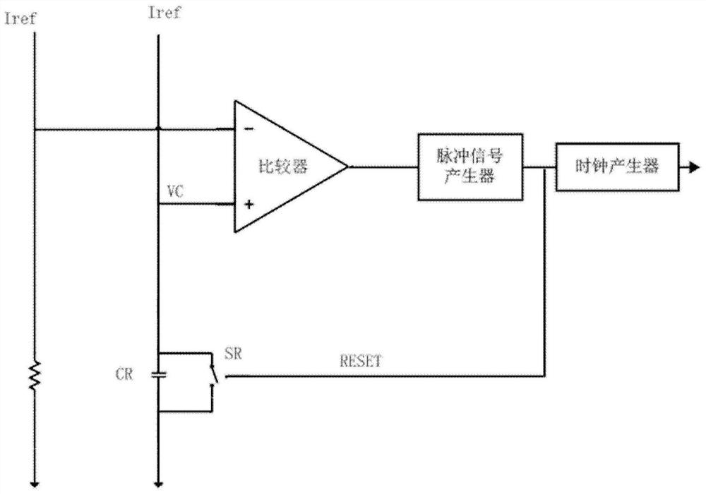
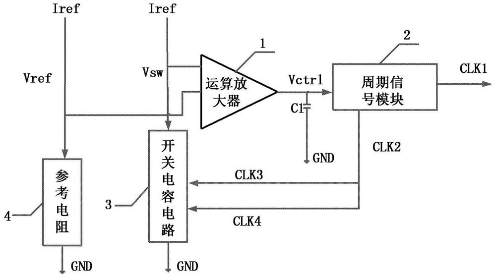
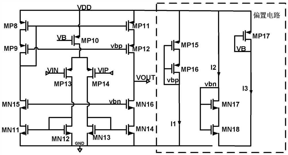
[0045] Due to the use of a comparator structure in the prior art, the power consumption is large. In addition, the delay time of the comparator and the pulse generating circuit is greatly affected by the temperature, so the overall output frequency is greatly affected by the temperature. In view of this, the present invention provides a kind of RC oscillator system, replaces comparator with the operation amplifier operating in the sub-threshold region, reduces power consumption; Operation amplifier, periodic signal module and switched capacitor circuit form negative feedback loop, The stability of the output frequency is ensured, and the technical defects of the prior art are effectively solved.

[0046] In order to make the object, technical solution and advantages of the present invention clearer, the present invention will be described in further detail below in conjunction with specific embodiments and with reference to the accompanying drawings.

[0047] figure 2 It is ...


PUM


Abstract

An oscillator system, comprising: an operational amplifier, working in the subthreshold region, two input terminals respectively connected to the first terminal of the reference resistor and the first terminal of the switched capacitor circuit, the output terminal outputs the first voltage, the reference resistor and the switch Each capacitor circuit is connected with a reference current; the positive end of the first capacitor is connected to the output end of the operational amplifier, and the negative end is grounded; the periodic signal module converts the DC component of the first voltage into a periodic signal, and outputs the second capacitor after the periodic signal is halved. A periodic signal; the second periodic signal after the periodic signal is halved is converted into a pair of anti-phase non-overlapping third periodic signal and fourth periodic signal; a switched capacitor circuit includes a second capacitor, according to the third periodic signal and the fourth periodic signal The fourth period signal controls charging and discharging of the second capacitor. Among them, the operational amplifier, the periodic signal module and the switched capacitor circuit form a negative feedback loop to ensure the stability of the output frequency, and the operational amplifier works in the sub-threshold region, and the power consumption of the oscillator system is extremely low.

Description

technical field [0001] The invention relates to the field of integrated circuit design, in particular to an oscillator system. Background technique [0002] In the ultra-low power consumption micro control unit MCU chip, a clock with low power consumption, high power supply voltage and temperature stability is usually required to realize the timing function required by the system. [0003] Conventional RC oscillator circuits such as figure 1 As shown, including: comparator, current source, pulse generating circuit, clock generating circuit, reference resistor, capacitor and switch. One current flows through the reference resistor to generate a reference voltage Vref, which is connected to the negative phase terminal of the comparator, and the other current charges the capacitor to generate a voltage Vc. The positive terminal of the capacitor is connected to the positive phase terminal of the comparator, and the negative terminal is grounded. The traditional RC oscillator c...

Claims


Application Information

Patent Timeline
Patent Type & Authority Patents(China)
IPC IPC(8): H03K3/011
CPCH03K3/011
Inventor 胡安俊胡晓宇乔树山黑勇
Owner INST OF MICROELECTRONICS CHINESE ACAD OF SCI
Why Eureka
Try Eureka