Accelerated test and prediction method for service life of laser optical component

A technology of optical components and testing methods, which is applied in the direction of testing optical performance, measuring devices, scientific instruments, etc., can solve problems such as the inability to directly apply the reliability evaluation of optical systems, the inability to obtain the service life of components, and the high cost of testing, so as to achieve high confidence Accuracy and practicability, high test efficiency, simple test method

Active Publication Date: 2018-07-20
LASER FUSION RES CENT CHINA ACAD OF ENG PHYSICS
View PDF10 Cites 4 Cited by
  • Summary
  • Abstract
  • Description
  • Claims
  • Application Information

AI Technical Summary

Problems solved by technology

[0007] The purpose of the present invention is to solve the problems of the traditional large-aperture optical device life test in the prior art, such as the test result confidence, low applicability, low test efficiency and high test cost caused by applying the traditional general product life test method. The evaluation parameters of device damage characteristics (damage threshold or damage growth factor, etc.) cannot be directly applied to the reliability evaluation of optical systems and cannot obtain the service life of components under arbitrary flux irradiation. Life Accelerated Testing and Prediction Methods

Method used


Image

  • Accelerated test and prediction method for service life of laser optical component
  • Accelerated test and prediction method for service life of laser optical component
  • Accelerated test and prediction method for service life of laser optical component

Examples


Embodiment 1

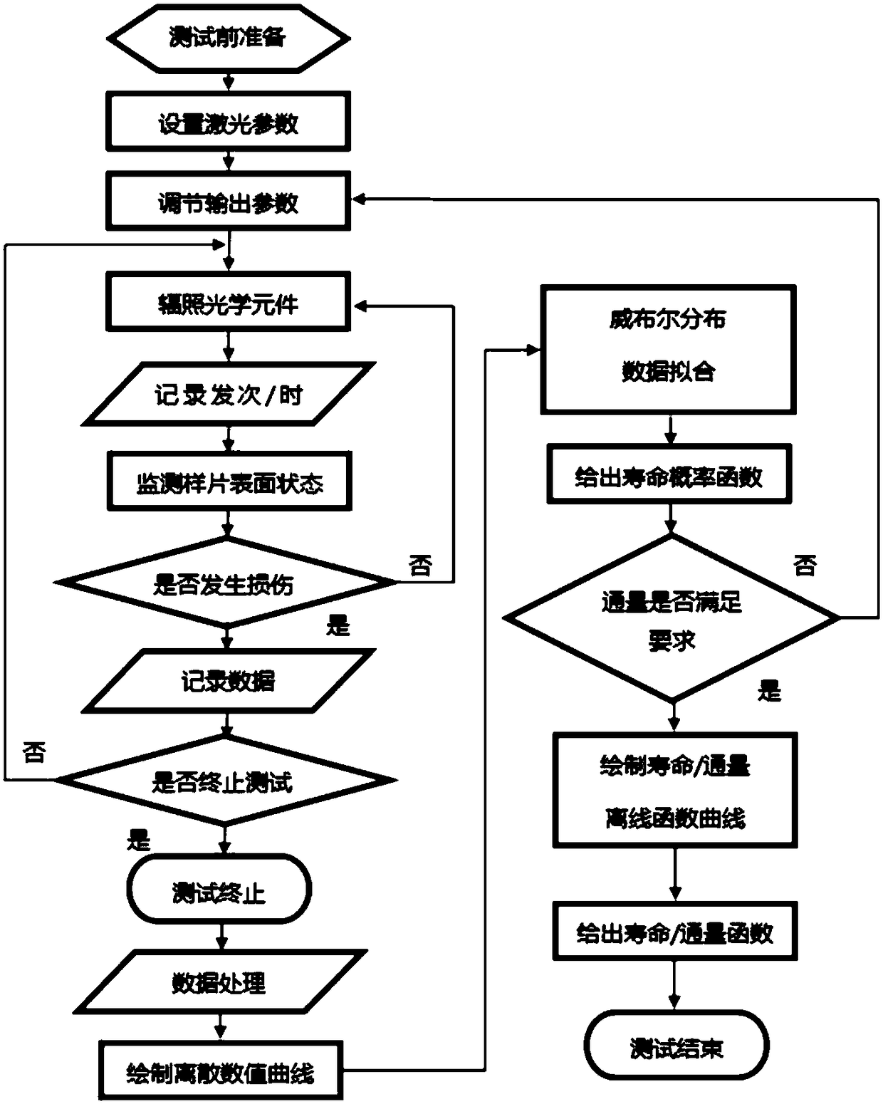
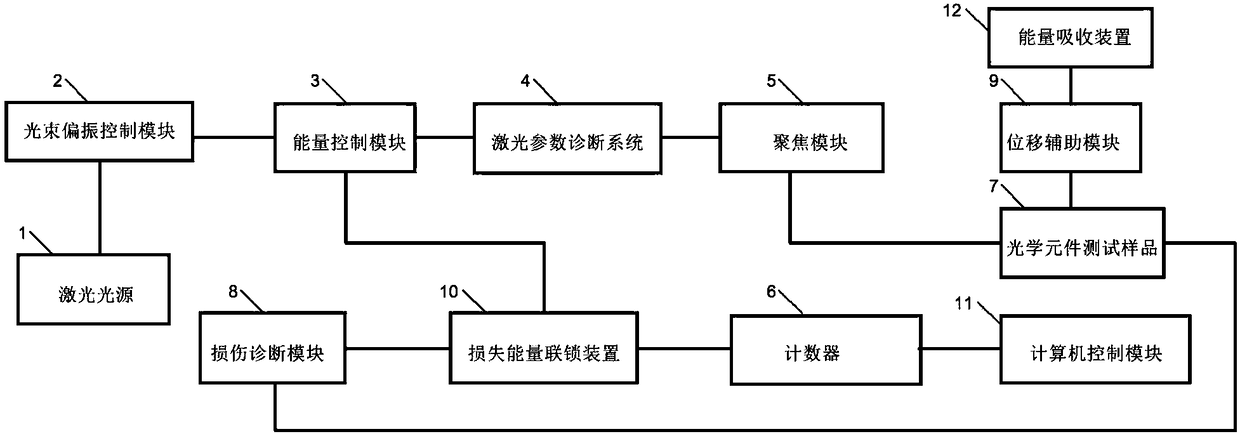
[0081] The schematic diagram of the life accelerated test system in the present invention refers to the appended figure 2 , including a laser light source 1 processing emission module and an optical element test sample 7, a counter 6, a damage diagnosis module 8, a displacement auxiliary module 9, a damage energy interlocking device 10, an energy control module 3, a computer control module 11 and an energy absorption device 12, The optical element test sample 7 is arranged on the displacement auxiliary module 9; the displacement auxiliary module 9 adjusts the position of the optical element test sample 7;

[0082] The laser light source 1 processes the emission module, and emits laser light with specific laser parameters to irradiate the optical element test sample 7;

[0083] The damage diagnosis module 8 detects the damage degree of the optical element test sample 7, and sends out a damage signal when it detects that the optical element test sample 7 is irreversibly damaged...

Embodiment 2

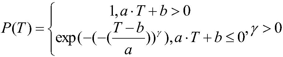
[0130] On the basis of Example 1, the lifetime flux function under a specific lifetime probability is obtained;

[0131] Substituting the expected laser flux into the lifetime flux function to obtain the estimated service life under the expected laser flux and specific lifetime probability;

[0132] In the case of not specifying the life probability, calculate the life corresponding to the maximum life probability and the minimum life probability under a specific flux, and obtain the expected result of the service life range under a specific flux.

[0133] The life cycle or time of the present invention is not the damage threshold or damage growth factor under the action of finite laser pulses or time, the test results are more in line with the actual use requirements of laser devices, and the test results can be directly applied to the reliability analysis of optical systems, and can be The service life of optical components under any flux is predicted, and the test efficienc...


PUM


Abstract

The invention discloses an accelerated test and prediction method for the service life of a laser optical component so that a problem that the service life of the large-caliber optical component underrandom flux illumination can not be obtained in the prior art can be solved. The method comprises: fitting is carried out by using a transmitting number or time as an independent variable and a corresponding service life probability as a dependent variable to obtain a service life probability function of a large-caliber optical component under a specific laser parameter; and the irradiation fluxof illuminating laser with a set parameter is changed to obtain a service life probability curve of the large-caliber optical component under different irradiation fluxes and data fitting is carried out on the function to obtain a service life flux function under the specific service life probability. According to the invention, accelerated testing of the service life of the laser optical component is realized; the test time is shortened. With the test result, the service life of the large-caliber optical component under the specific flux can be obtained; and on the basis of the classical reliability theory, the reliability analysis and prediction are carried out on the laser large-caliber optical component in the laser system. The accelerated test and prediction method is suitable for theservice life testing field of the large-caliber optical component.

Description

technical field [0001] The invention relates to the field of life testing of laser optical components, in particular to a method for accelerated testing and prediction of the service life of laser optical components. Background technique [0002] Laser optical components will suffer from laser-induced damage under the action of lasers, especially high-power / high-energy lasers. One of the existing evaluation indicators is the probability damage threshold. Refer to the prior art 1, ISO 21254 (part1~part4), Lasers and laser-related equipment–Test methods for laser-induced damage threshold has relevant instructions, which believe that optical components will not be damaged under the damage threshold; the second evaluation index is the damage growth factor, refer to the prior art 2, Zhi M.Liao, *B. Raymond, J.Gaylord, R.Fallejo, J.Bude, and P.Wegner, "Damagemodeling and statistical analysis of optics damage pertableance in MJ-classlaser systems", [J].OPTICS EXPRESS Vol.22,No.23(2...

Claims


Application Information

Patent Timeline
Patent Type & Authority Applications(China)
IPC IPC(8): G01M11/02G01N17/00G06F17/18
CPCG01M11/02G01N17/004G06F17/18
Inventor 巴荣声李杰丁磊周信达郑垠波徐宏磊陈波李文洪姜宏振刘勇李东刘旭张霖杨一郑芳兰于德强马可石振东马骅任寰张保汉景峰
Owner LASER FUSION RES CENT CHINA ACAD OF ENG PHYSICS
Why Eureka
Try Eureka