Laser and water jet combined machining system

A composite processing and water jet technology, which is used in laser welding equipment, metal processing equipment, manufacturing tools, etc., can solve problems that hinder the application of laser high-pressure water jet composite processing technology, cannot block the optical path of the laser exit part, and cannot isolate the anti-sputtering device. Interference and other problems, to achieve the effect of improving the processing effect, stabilizing the optical path, and reducing the width of the scribing and cutting line

Pending Publication Date: 2018-07-27
GUILIN UNIV OF ELECTRONIC TECH
View PDF0 Cites 12 Cited by
  • Summary
  • Abstract
  • Description
  • Claims
  • Application Information

AI Technical Summary

Problems solved by technology

[0007] There are also designs to install an anti-sputtering device in the laser optical path, but the additional anti-sputtering device must not block the optical path from the laser exit part to the surface of the workpiece, so the anti-sputtering device cannot isolate the interference of the laser optical path by the strong sputtering of the high-pressure jet
[0008] In short, the problem that jet sputtering affects the laser beam during the operation of the existing laser high-pressure water jet composite processing system is hindering the application of this laser high-pressure water jet composite processing technology.

Method used


Image

  • Laser and water jet combined machining system
  • Laser and water jet combined machining system
  • Laser and water jet combined machining system

Examples


Embodiment Construction

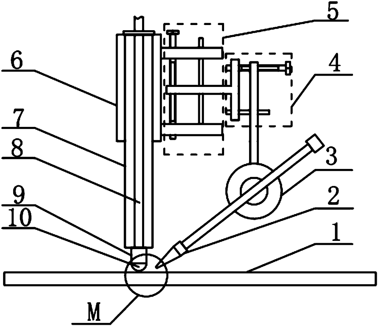
[0027] The structure of the embodiment of the laser water jet composite processing system is as follows figure 1 As shown, it includes a jet nozzle 2 connected with a water tank, a laser, and a workbench. The workbench surface is a horizontal plane, and the workpiece 1 is fixed on the workbench surface. The jet nozzle 2 emits a water jet, and the water jet falls on the processing path of the workpiece surface. The center line of the laser beam generated by the laser is perpendicular to the table surface.

[0028] The laser beam generated by the laser in this example propagates in the guiding optical fiber 8. The guiding optical fiber 8 of this example is located in the protective casing 7, and there is a supporting casing 6 outside the protective casing 7. The supporting casing 6 fixes the protective casing 7 and Fixed connection with the rack. The end of the guiding optical fiber 8 is connected to the diamond guiding head 10 via the laser shaper 9.

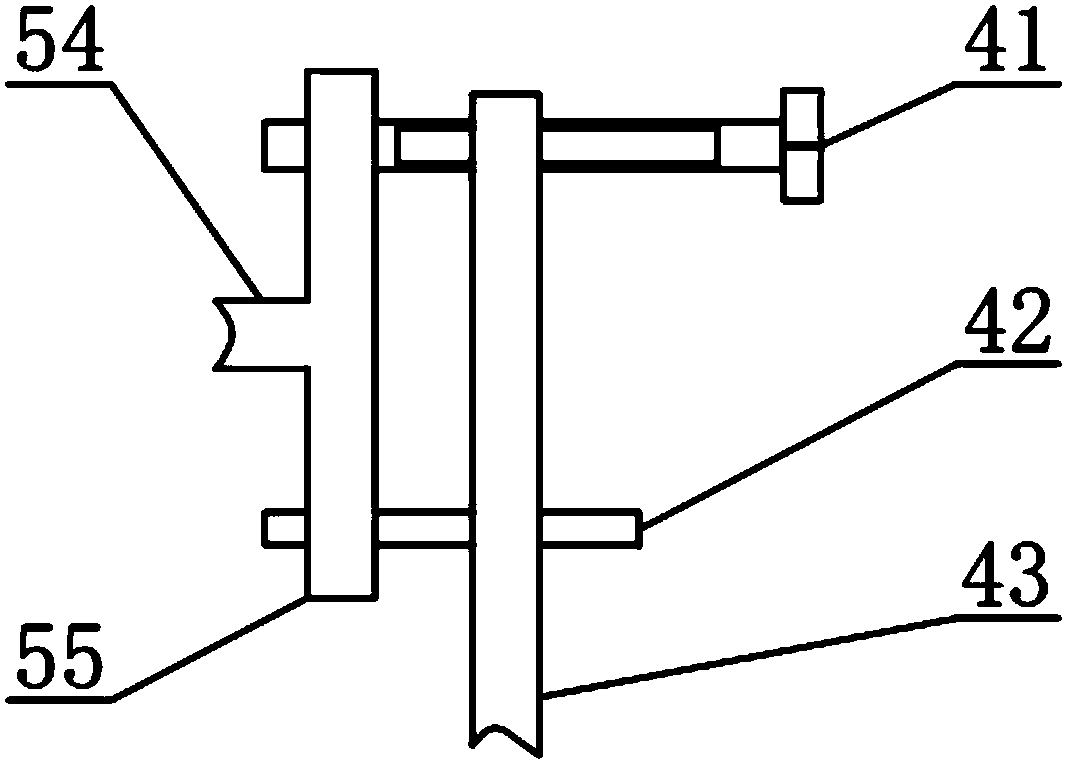
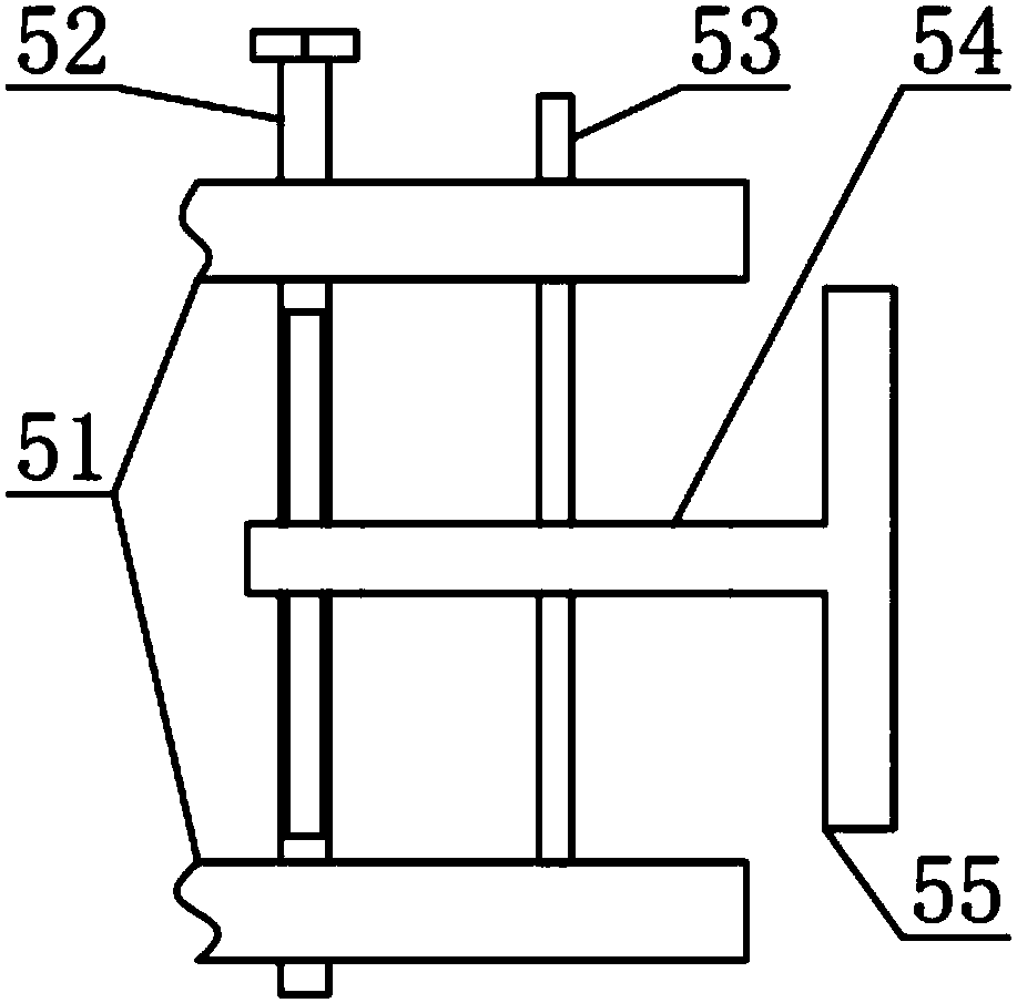
[0029] Such as Figure 4 wit...


PUM

PropertyMeasurementUnit
wavelengthaaaaaaaaaa
diameteraaaaaaaaaa

Abstract

The invention provides a laser and water jet combined machining system. According to the laser and water jet combined machining system, a jet nozzle ejects water jet out and the water jet drops on a machining route of the surface of a workpiece; a laser beam generated by a laser device is propagated in a guiding optical fiber in a protection shell body and the tail end of the guiding optical fiberis connected with a diamond guiding head; the distance between a light guiding end of the diamond guiding head and the surface of the workpiece is less than 100 micrometers; laser gathers into straight light beam output by multiple total reflection in the diamond guiding head and acts on the machining route of the surface of the workpiece in water directly. According to the system, the light pathof the laser beam is located in the protection shell body, so that it is guaranteed that the light beam is undisturbed by sputtering mist of the water jet during propagation; materials on the presetmachining route can be accurately and efficiently removed by the synergistic action of the laser beam and the high-pressure water jet, so that the light path of laser is stable, the radius of a laserspot is reduced, the cutting-up line width is reduced and the machining accuracy and quality are improved.

Description

Technical field [0001] The invention relates to a laser water jet composite processing technology, in particular to a laser water jet composite processing system guided by a diamond. Background technique [0002] The laser water jet composite processing technology uses laser to irradiate the workpiece. The local heating temperature of the workpiece increases, the local high temperature material softens and the mechanical strength decreases. While the laser is irradiated, a high-pressure liquid jet is used to impact the laser heated area on the workpiece, and the jet removes the mechanical strength. The reduced material completes the processing of the workpiece. [0003] Since the laser water jet composite processing technology does not melt or vaporize the phase change of the workpiece material during the processing process, the processing technology has the advantage of less thermal damage. In addition, when the high-speed jet impacts the processing part, the strong convection co...

Claims


Application Information

Patent Timeline
Patent Type & Authority Applications(China)
IPC IPC(8): B23P23/00
CPCB23K26/0093
Inventor 刘清原龙芋宏鲍家定周嘉黄宇星焦辉赵要武
Owner GUILIN UNIV OF ELECTRONIC TECH
Why Eureka
Try Eureka