Environment-friendly type continuous feeding device and method of smelting furnace

A technology of feeding device and melting furnace, applied in the direction of furnace types, furnaces, crucible furnaces, etc., can solve the problems of increasing energy consumption of melting furnaces, harsh working environment, and reducing combustion temperature, so as to improve the working environment of the workshop and improve the operability The effect of improving the sealing performance

Pending Publication Date: 2018-08-03
河南省冶金研究所有限责任公司
View PDF8 Cites 1 Cited by
  • Summary
  • Abstract
  • Description
  • Claims
  • Application Information

AI Technical Summary

Problems solved by technology

[0005] 1. Poor sealing and high energy consumption: due to the positive pressure environment in the melting furnace, a large amount of hot air in the furnace will be discharged to the outside of the furnace at the feeding port, which reduces the combustion temperature in the furnace and increases the energy consumption of the melting furnace
[0006] 2. Severe unorganized emissions: due to the positive pressure environment in the smelting furnace, there will be a large amount of unorganized lead fume, sulfur dioxide, arsenic, mercury, cadmium and other waste gas pollutants escaping from the feed port, and the working environment in the area is harsh. Serious health hazards for workers at nearby stations and residents near businesses
[0007] 3. Poor safety: Since the mouth of the smelting furnace is basically horizontal, there are certain hidden dangers in the maintenance of the equipment at the feed inlet

Method used


Image

  • Environment-friendly type continuous feeding device and method of smelting furnace
  • Environment-friendly type continuous feeding device and method of smelting furnace

Examples


Embodiment Construction

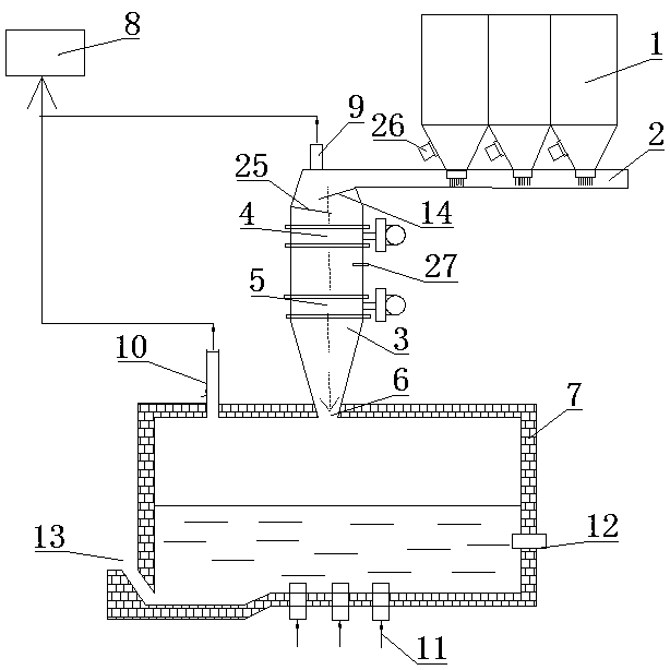
[0037] An environment-friendly continuous feeding device for a smelting furnace, such as Figure 1-2 As shown, it includes the steady flow bin 1, the airtight conveyor belt 2, the feeder 3 and the smelting furnace 7 which are connected in sequence; A vibrating motor 26 is provided on the outside of the lower part of the warehouse, and the outlet at the bottom of the steady flow warehouse 1 is located above the head end of the airtight conveyor belt 2; A baffle structure 4 and a second baffle structure 5, a material level gauge 27 is arranged above the second baffle structure 5; a feeder inlet is provided on the feeder 3, and the feeder inlet is arranged at the lower end of the airtight conveyor belt 2 , the inlet of the feeder 3 is provided with deflectors 14 matched with the airtight conveyor belt 2, and buffer plates 25 are arranged staggeredly below the deflectors 14; The tuyere 9 and the exhaust outlet 9 are provided with an exhaust fan; the top of the smelting furnace 7 ...


PUM


Abstract

The invention belongs to the field of smelting furnace equipment and particularly relates to an environment-friendly type continuous feeding device of a smelting furnace. The environment-friendly typecontinuous feeding device of the smelting furnace comprises a steady flow bin, an airtight conveying belt, a feeder and the smelting furnace which are connected in sequence. A bottom outlet of the steady flow bin is arranged above the head end of the airtight conveying belt. The feeder comprises a feeder pipeline, and a first baffle structure and a second baffle structure are sequentially connected in the feeder pipeline through flanges from top to bottom. The feeder is provided with a feeder inlet, the feeder inlet is arranged below the tail end of the airtight conveying belt and provided with a flow guide plate matched with the airtight conveying belt, and a buffer plate is arranged below the flow guide plate in a staggered mode. The upper side of the smelting furnace is provided with afeeding inlet matched with an outlet of the feeder. The invention further relates to an environment-friendly type continuous feeding method of the smelting furnace. According to the environment-friendly type continuous feeding device and method of the smelting furnace, the structure is simple and continuous feeding can be achieved.

Description

technical field [0001] The invention belongs to the field of smelting furnace equipment, and in particular relates to an environment-friendly continuous feeding device and method for a smelting furnace. Background technique [0002] In recent years, my country's lead smelting technology has been greatly improved, occupying an important position in the world's lead smelting industry. At present, most domestic lead smelters use double bottom blowing process, bottom blowing + side blowing process or double side blowing process to smelt lead. The core is to react oxidation and reduction in different smelting processes. This process can well solve the problem of lead smelting flue gas SO2 acid production and lead fume pollution. In the process of raw material batching, this process adopts closed weighing scales to measure, and the mixing and granulation of lead materials are carried out in closed facilities. The process is simple, the environment is good, and the characteristics...

Claims


Application Information

Patent Timeline
Patent Type & Authority Applications(China)
IPC IPC(8): F27B14/16F27D17/00
CPCF27B14/0806F27D17/008F27B2014/0812
Inventor 鲁然英常德政张继光施琪刘世豪韩双城
Owner 河南省冶金研究所有限责任公司
Why Eureka
Try Eureka