
Coating film, manufacturing method therefor, and PVD apparatus

A manufacturing method and coating technology, which can be used in chemical instruments and methods, sputtering plating, ion implantation plating, etc., can solve the problems of inability to be used as a sliding member coating, low hardness, poor wear resistance, etc.

Active Publication Date: 2018-08-03
NIPPON ITF +1
View PDF20 Cites 9 Cited by
  • Summary
  • Abstract
  • Description
  • Claims
  • Application Information

AI Technical Summary

Problems solved by technology

Therefore, with sp 2 The carbon atoms in the hybrid orbitals are more than 70% and sp 2 / sp 3 Ratio becomes very large and becomes 2.3 to ∞, only a hard carbon film with low hardness and poor wear resistance can be obtained, and it cannot be used as a coating film for sliding members
[0014] Furthermore, Patent Document 6 proposes a DLC film having a thickness of at least 10 μm and sp 3 A DLC film for a piston ring containing a hydrogen-free ta-c type DLC at a ratio of at least 40 atomic %, and the outer 1 μm to 3 μm of the ta-c type DLC film is reduced by doping B, O, and Si. the sp 3 Ratio, excellent friction during leveling, improved heat resistance in an insufficiently wet environment, and has an effect of suppressing marking, but it still does not fully coexist with chip resistance and abrasion resistance

Method used


Image

  • Coating film, manufacturing method therefor, and PVD apparatus
  • Coating film, manufacturing method therefor, and PVD apparatus
  • Coating film, manufacturing method therefor, and PVD apparatus

Examples


no. 1 Embodiment approach

[0162] 1. Substrate

[0163] In the present invention, the base material for forming the hard carbon film as the coating film is not particularly limited, and non-ferrous metals or ceramics, hard composite materials, and the like can be used in addition to iron. Specifically, carbon steel, alloy steel, quenched steel, high-speed tool steel, cast iron, aluminum alloy, Mg alloy or superhard alloy, etc., if the film formation temperature of the hard carbon film is considered, it is preferably at A substrate whose properties do not deteriorate significantly at temperatures exceeding 200°C.

[0164] 2. Middle layer

[0165] When forming a hard carbon film, it is preferable to provide an intermediate layer on a substrate in advance. Thereby, the adhesion between the base material and the hard carbon film can be improved, and when the hard carbon film is worn, the exposed intermediate layer can function as wear resistance.

[0166] As such an intermediate layer, a layer using at l...

Embodiment 1

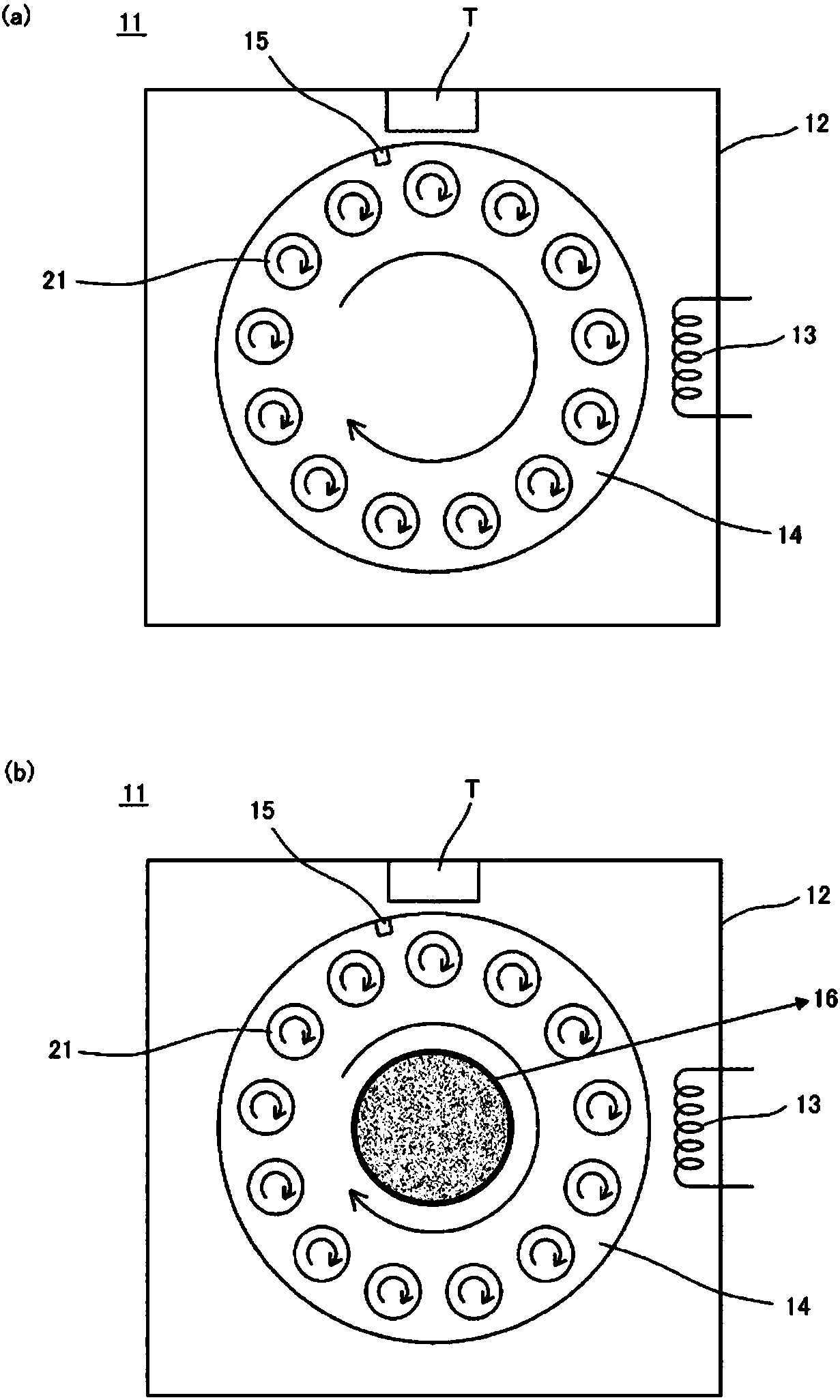
[0249] In Example 1, the use includes image 3 In the arc PVD apparatus of the film-forming furnace 11 shown in (a), hard carbon with a total film thickness of 4.7 μm is deposited on the surface of the substrate 21 by the same method as that of the coating film manufacturing method of the above-mentioned embodiment. Film into film.

[0250] Specifically, after placing the substrate with the CrN layer on the rotation and revolving jig 14 which is also the substrate support device, it is placed in the furnace 11 of the arc type PVD device, and a metal Cr layer with a thickness of 0.2 μm is coated as an intermediate layer. , and then start the hard carbon film formation using a graphite cathode.

[0251] At this time, the base material 21 was rotated and revolved at a rotation speed of 39 rpm and a revolution of 4 rpm. In addition, regarding the temperature conditions during film formation, arc discharge was performed at a bias voltage of -700V and an arc current of 40A for 10 ...

Embodiment 2~ Embodiment 21

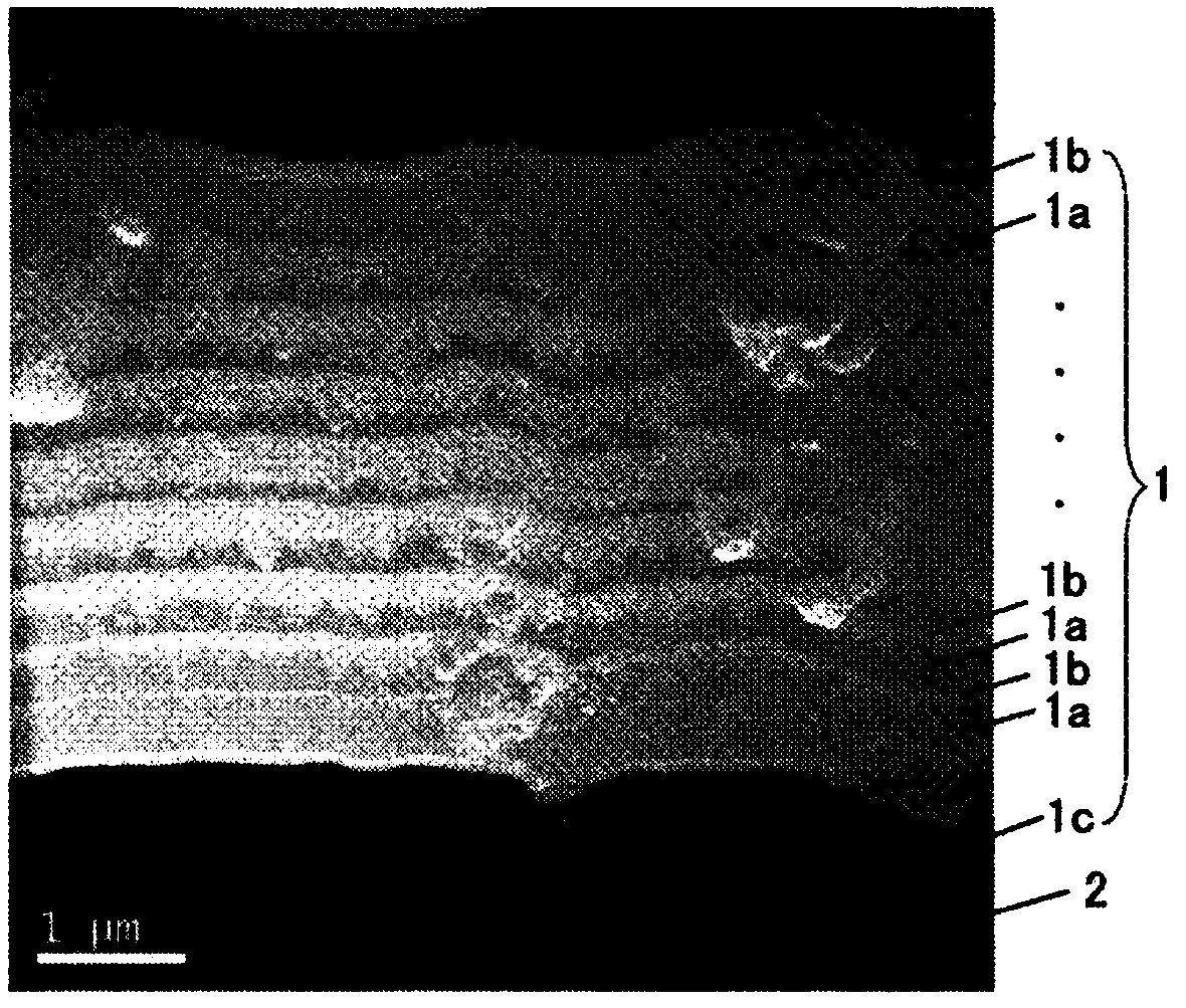
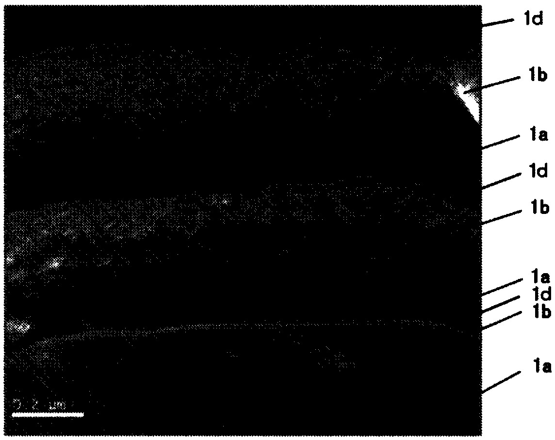
[0272] From the results of Experiment 1, it was confirmed that when a black hard carbon layer and a white hard carbon layer are laminated to form a coating film, wear resistance, chip resistance, low friction, Peeling resistance and durability (lifetime) are good, so in the following experiment 2, in the same manner as in Example 1, in the structure in which the black layer and the white layer are alternately laminated, the outermost layer is the white layer, and the total For the hard carbon layer with a film thickness of 4.8 μm to 5.8 μm, various film formation conditions were changed, and the sp of the black hard carbon layer was adjusted to 2 / sp 3 Than, sp of the white hard carbon layer 2 / sp 3 The thickness of the black hard carbon layer and the thickness of the white hard carbon layer were different, and the coating films of Examples 2 to 21 as shown in Table 2 were formed.

[0273] [Table 2]

[0274]

[0275] 2. Evaluation

[0276] The coating films of Examples...


PUM

PropertyMeasurementUnit
hardnessaaaaaaaaaa
hardnessaaaaaaaaaa
roughnessaaaaaaaaaa

Abstract

The purpose of the invention is to provide technology, which, in addition to being capable of forming thick hard carbon films of excellent durability even using PVD, is able to establish both chippingresistance and abrasion resistance in the formed hard carbon film and able to improve low friction properties and peeling resistance. Provided is a coating film to coat the surface of a substrate, the coating film having a total film thickness of greater than 1 [mu]m to 50 [mu], wherein: when a cut surface is observed using bright field TEM images, white hard carbon layers that are shown as relatively white and black hard carbon layers that are shown as black are alternately laminated in the thickness direction; and the white hard carbon layers have regions that have grown in a fan-shape in the thickness direction. Provided is a coating film manufacturing method for forming the coating film on the surface of a substrate using PVD, wherein conditions for film formation on the substrate arecontrolled so that the substrate repeatedly alternates temperature increase and temperature decrease between a low temperature range of greater than 50 DEG C to 200 DEG C and a high temperature rangeof greater than 200 DEG C to 300 DEG C, and the substrate is rotated and / or made to revolve.

Description

technical field [0001] The present invention relates to a coating film, its manufacturing method, and a Physical Vapor Deposition (Physical Vapor Deposition, PVD) device, and more specifically, to a coating film suitable as a coating film for various sliding members, its manufacturing method, and its The PVD device used in the above-mentioned manufacturing method. Background technique [0002] In recent years, in various industrial fields, especially in the automotive field, there has been active research on forming a hard carbon film as a coating film on the surface of components that require sliding properties such as engine (engine) substrates and other mechanical substrates. . [0003] The hard carbon film is usually called by various names such as diamond-like carbon (Diamond Like Carbon, DLC) film, amorphous carbon film, i-carbon film, diamond-like carbon film, etc., and is not crystalline in structure and is classified as Amorphous. [0004] Moreover, with regard t...

Claims


Application Information

Patent Timeline
Patent Type & Authority Applications(China)
IPC IPC(8): C23C14/06C01B32/15C01B32/18C01B32/182C23C14/32F16J9/26
CPCF16J9/26C23C14/548C23C28/044C23C28/046C23C14/0605C23C14/325C23C14/505C23C14/541B32B9/007C23C14/14
Inventor 森口秀树柴田明宣大城竹彦伊东义洋冈崎孝弘杉浦宏幸
Owner NIPPON ITF
Learn More