
Orthogonal volume holographic grating solid-state laser

A technology of solid-state lasers and volume holographic gratings, which is applied to lasers, laser components, laser components, etc., can solve problems such as complex optical paths, and achieve the effect of power increase

Active Publication Date: 2020-02-11
AVIC BEIJING AERONAUTICAL MFG TECH RES INST
View PDF8 Cites 0 Cited by
  • Summary
  • Abstract
  • Description
  • Claims
  • Application Information

AI Technical Summary

Problems solved by technology

The light path is very complicated

Method used


Image

  • Orthogonal volume holographic grating solid-state laser
  • Orthogonal volume holographic grating solid-state laser
  • Orthogonal volume holographic grating solid-state laser

Examples


Embodiment 1

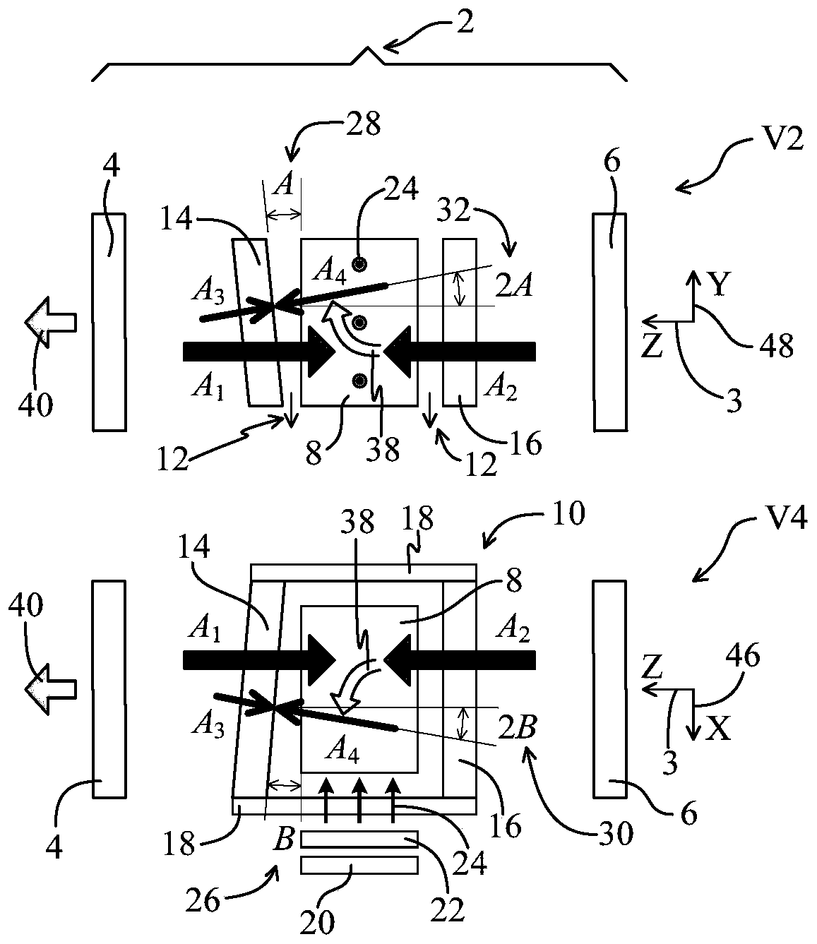
[0026] like figure 1As shown, it is a schematic structural diagram of a single-side pumping mode of an orthogonal volume holographic grating solid-state laser according to an embodiment of the present invention, including a V2 plane view of the Y-Z plane and a V4 plane view of the X-Z plane. The orthogonal volume holographic grating solid-state laser includes a laser resonant cavity 2 , an activation element 8 and a pumping source 20 . The laser resonator 2 is a linear resonator, using parallel planar cavities. Non-parallel planar cavities, or other cavity types can also be used. One reason for using non-parallel planar cavities is to compensate for the additional optical path inside the active element 8 due to one-sided pumping. The laser resonator 2 includes an output mirror 4 and a high reflection mirror 6 which are oppositely arranged. A strip-shaped activation element 8 in the shape of a cuboid is arranged in the laser resonator 2 . The activation element 8 is arrange...

Embodiment 2

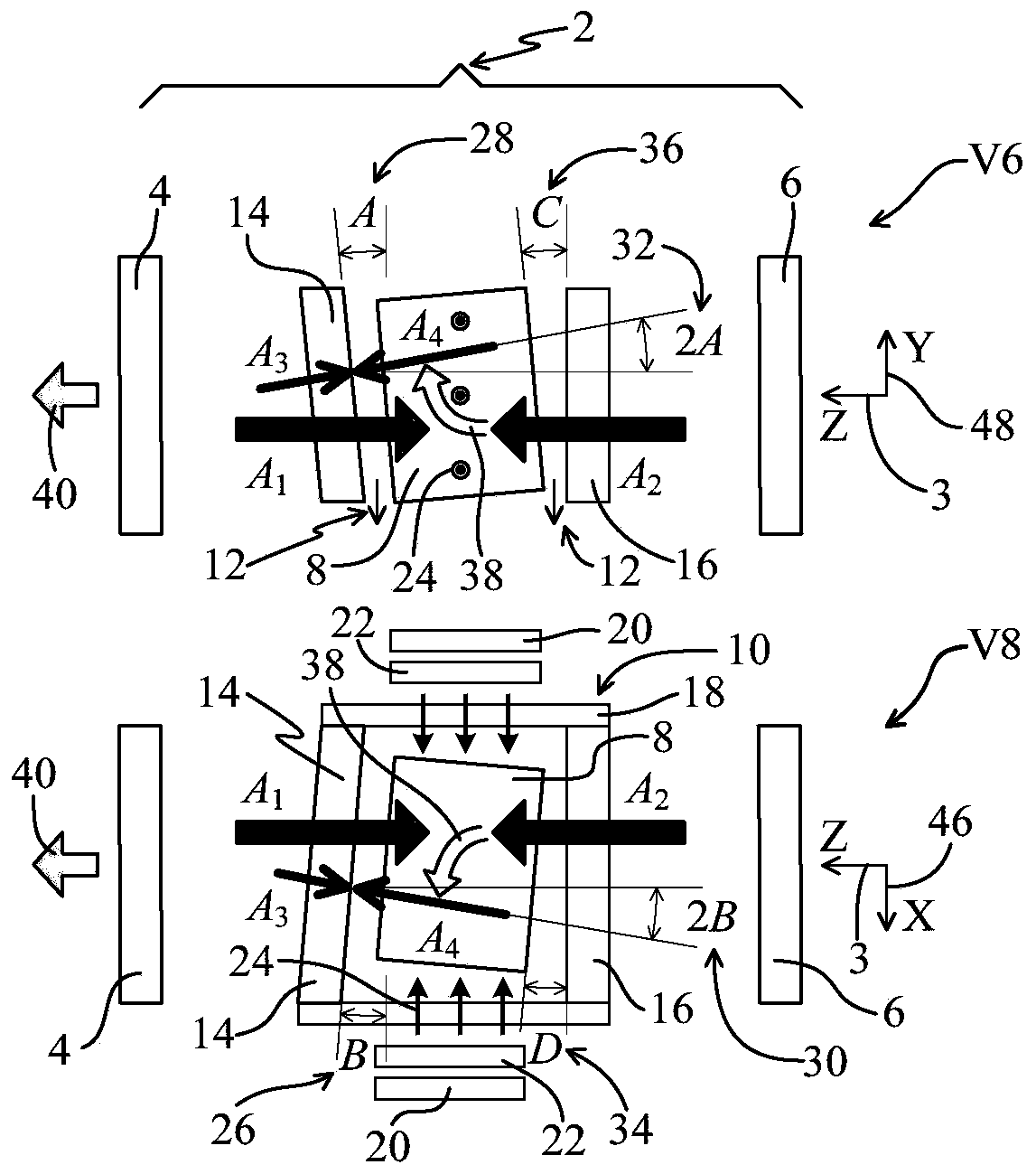
[0034] like figure 2 As shown, it is a schematic structural diagram of the opposite-side pumping mode of an orthogonal volume holographic grating solid-state laser according to an embodiment of the present invention, including the V6 plane view of the Y-Z plane and the V8 plane view of the X-Z plane. The difference between Embodiment 2 and Embodiment 1 lies in that two sets of pumping sources and their coupling devices are used for contralateral pumping and the activation element 8 is placed obliquely.

[0035] As shown in the view of V8, the pumping source 20 is arranged symmetrically on both sides of the front and back of the activation element 8, the pumping source is a semiconductor laser pumping source, and the pumping light 24 emitted by the pumping source 20 passes through the beam shaping system, that is, the coupling device 22 , through the pumping window glass sheet 18 of the liquid cooling chamber 10 , and irradiate on both sides of the activation element 8 . The ...


PUM

PropertyMeasurementUnit
thicknessaaaaaaaaaa
Gain coefficientaaaaaaaaaa
reflectanceaaaaaaaaaa

Abstract

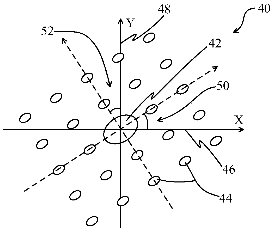
The embodiment of the invention provides an orthogonal holographic grating solid laser. The laser comprises a laser resonant cavity, a liquid cooling cavity, an activating element and a pumping source, wherein the laser resonant cavity is a linear resonant cavity and comprises an output mirror and a high-reflection mirror; the liquid cooling cavity comprises an inclined glass sheet, a vertical glass sheet and a pumping window glass sheet; the pumping source is used for emitting pumping light to the side surface of a cuboid-shaped activating element through the coupling device; the coupling device is used for coupling the pumping light emitted by the pumping source into the activating element. The minimum distance between the inclined glass sheet and the oscillating laser light-passing surface of the activating element is 0. 5mm, and the inclination angles of the inclined glass sheet in the two orthogonal directions range from 0.5 milliradians to 0.1 milliradians. Degeneration four wavemixing conditions are simultaneously met in two orthogonal planes inside the active element. The average threshold pumping power density of the degeneration four wave mixing is larger than 300 wattsper square centimeter. Before a mold selection device is added, the laser outputs orthogonal fraunhofer diffraction patterns.

Description

technical field [0001] The invention relates to the technical field of solid lasers, in particular to an orthogonal volume holographic grating solid laser. Background technique [0002] The confocal cavity theory of the laser principle points out that the common fundamental transverse mode solid-state laser has a very small Rayleigh length, for example, less than 1 mm (Dietrich, J. et al. 2008. Opt. Laser. Eng., 46(10) , 705), resulting in a small radius of the basal transverse mode waist spot. This makes it possible that if the aperture of the cavity mirror and laser gain medium of the laser resonator is much larger than the laser wavelength, for example, the laser wavelength is 1 micron, and no transverse mode selection device is added in the cavity, the laser will output multimode laser. As the pump power increases, more transverse modes gain more than the threshold and start to oscillate. At the same time, the optical distortion and thermal depolarization caused by the...

Claims


Application Information

Patent Timeline
Patent Type & Authority Patents(China)
IPC IPC(8): H01S3/1055H01S3/081H01S3/04H01S3/106
CPCH01S3/04H01S3/0401H01S3/081H01S3/1055H01S3/106
Inventor 王学军
Owner AVIC BEIJING AERONAUTICAL MFG TECH RES INST
Learn More