Manufacturing method and testing method of piezoelectric ceramic sensor for concrete ERT imaging

A technology of piezoelectric ceramics and a manufacturing method, which is applied to instruments, measuring devices, scientific instruments, etc., can solve the problems of affecting the sending and receiving angle, inconvenient adjustment, low strength, etc., to avoid interference, good durability, and good compatibility. Effect

Inactive Publication Date: 2018-08-21
UNIV OF JINAN
View PDF11 Cites 2 Cited by
  • Summary
  • Abstract
  • Description
  • Claims
  • Application Information

AI Technical Summary

Problems solved by technology

The welding point of the piezoelectric ceramic sheet in the piezoelectric ceramic sensor will affect the sensitivity of the piezoelectric ceramic sensor due to the difference in geometric position. In the past, the method of fixing the welding point or randomly selecting the welding point has no basis for positioning the position of the welding point, resulting in The sensitivity of the sensor is not guaranteed, which limits the application range of piezoelectric ceramic sensors
[0004] In the existing ceramic sensor, the matching layer is bonded on the chip. Since the installed matching layer is easily tilted during operation, the outer end surface of the matching layer is not parallel to the electrode surface of the chip (the end surface at the end of the bonding matching layer), which affects the transmission and reception. Angle; the sensor vibrates when it works, which affects its life and is easy to fall off; the choice of adhesive for bonding has an impact on the effect of sending and receiving ultrasonic waves; the two wires are respectively connected to the two electrodes of the piezoelectric ceramic chip, and the matching layer is connected to the piezoelectric ceramic chip. One electrode (usually the n

Method used


Image

  • Manufacturing method and testing method of piezoelectric ceramic sensor for concrete ERT imaging
  • Manufacturing method and testing method of piezoelectric ceramic sensor for concrete ERT imaging
  • Manufacturing method and testing method of piezoelectric ceramic sensor for concrete ERT imaging

Examples


Embodiment 1

[0044] In the present invention, the piezoelectric ceramic sheet is respectively used for the signal driver and the signal sensor. The signal driver should use the piezoelectric ceramic sheet as PZT-4, and the signal sensor should use the piezoelectric ceramic sheet as PZT-4. The PZT-4 and PZT-4 piezoelectric elements used in this study were produced by Baoding Bofa Sensor Sales Co., Ltd. PZT-4 and PZT-4 are respectively used as receiving drive elements and emitting drive elements to prepare receiving piezoelectric ceramic sensors and emitting piezoelectric ceramic sensors.

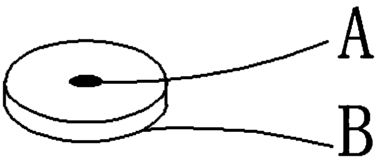
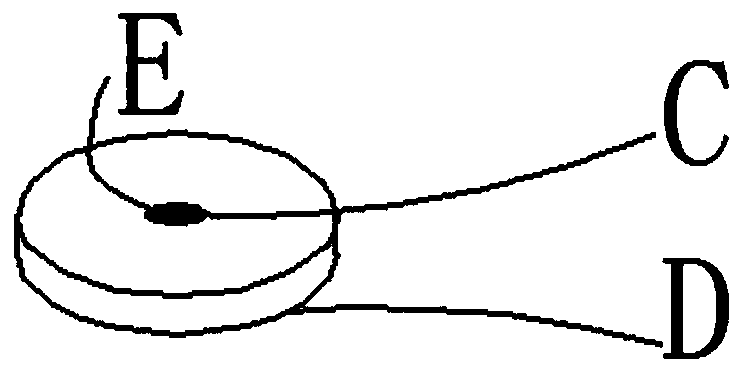
[0045] In the present invention, a piezoelectric ceramic sheet with a diameter of 10mm and a thickness of 1mm is selected. The positive and negative electrodes of the piezoelectric ceramic sheet are respectively located at the positive and negative poles, and the surface with red dots is the positive electrode. Wipe the surface of the sensor with a cotton swab dipped in acetone reagent or absolute alcohol...

Embodiment 2

[0051] In the present invention, the piezoelectric ceramic sheet is used for the signal driver and the signal sensor respectively. The signal driver should use the piezoelectric ceramic sheet as PZT-4, and the signal sensor should use the piezoelectric ceramic sheet as PZT-5. The PZT-4 and PZT-5 piezoelectric elements used in this study were produced by Baoding Bofa Sensor Sales Co., Ltd. PZT-4 and PZT-5 are respectively used as receiving drive elements and emitting drive elements to prepare receiving piezoelectric ceramic sensors and emitting piezoelectric ceramic sensors.

[0052] The silicone resin includes 95 parts of epoxy resin, 20 parts of toluene solvent, 60 parts of polytetrafluoroethylene filling powder, and 2 parts of epoxy resin curing agent; bake the encapsulated piezoelectric ceramic sensor at 60°C , and keep it warm for 20 hours to cure the epoxy resin and reach a hardness of 12MPa.

[0053] The packaging material is 12 parts of cement, 0.9 part of epoxy resin,...

Embodiment 3

[0057] In the present invention, the piezoelectric ceramic sheet is respectively used for the signal driver and the signal sensor. The signal driver should use the piezoelectric ceramic sheet model PZT-5, and the signal sensor should use the piezoelectric ceramic sheet model PZT-5. The PZT-5 and PZT-5 piezoelectric elements used in this study were produced by Baoding Bofa Sensor Sales Co., Ltd. PZT-5 and PZT-5 are respectively used as the receiving drive element and the transmitting drive element to prepare the receiving piezoelectric ceramic sensor and the emitting piezoelectric ceramic sensor.

[0058] The silicone resin includes 110 parts of epoxy resin, 30 parts of toluene solvent, 70 parts of polytetrafluoroethylene filling powder, and 3 parts of epoxy resin curing agent; bake the encapsulated piezoelectric ceramic sensor at 60 °C , and keep it warm for 20 hours to cure the epoxy resin and reach a hardness of 16MPa.

[0059] The packaging material is 13 parts of cement, ...


PUM

PropertyMeasurementUnit
Diameteraaaaaaaaaa
Thicknessaaaaaaaaaa
Hardnessaaaaaaaaaa

Abstract

The invention discloses a manufacturing method and a testing method of a piezoelectric ceramic sensor for concrete ERT imaging. The manufacturing method comprises following steps: fixing A, B wires ona positive pole and a negative pole to form an emitting terminal; fixing C,D wires on the positive pole and the negative pole to form a receiving terminal; covering the wires by glue, painting glue on the positive pole, fixing a shielding wire E on the positive pole of the receiving terminal, smearing the conductive layer, painting glue again to cover the shielding wire; connecting the other endsof the wires of the emitting terminal and the receiving terminal to two sensor joints; preparing a mould, smearing a release agent, fixing a piezoelectric ceramic sheet in the center of the mould ina suspension state; evenly mixing cement and epoxy resin according to a mass ratio of 1:(1-2) to prepare an encapsulation material, pouring the encapsulation material into the mould with the fixed piezoelectric ceramic sheet to form a filled block; completely drying the filled block, and removing the mould to obtain the piezoelectric ceramic sensor. During the construction process, the sensor is buried in concrete to online real-time monitoring the corrosion of steel bars in a long term.

Description

technical field [0001] The invention belongs to the technical field of concrete structure health monitoring, and in particular relates to a manufacturing method and a testing method of a concrete ERT imaging piezoelectric ceramic sensor. technical background [0002] Sensing technology is a multidisciplinary modern science and engineering technology about obtaining information from natural sources, processing, transforming and identifying it. A sensor is a device with monitoring functions that is widely used in the fields of industry, agriculture, national defense, and medicine. It is called "electrical five senses", that is, by simulating the functions of human five senses, it monitors various non-electrical quantities. Piezoelectric ceramic sensors are devices that use the piezoelectric effect of piezoelectric ceramic sheets to convert stress or strain into voltage or charge, and then amplify and output through an amplifier. The piezoelectric ceramic sensor is composed of...

Claims


Application Information

Patent Timeline
IPC IPC(8): G01N17/04G01N17/00
CPCG01N17/006G01N17/04
Inventor 秦磊孙世栋朱晓军任宏伟董必钦邢峰田凯歌
Owner UNIV OF JINAN
Why Eureka
Try Eureka