

Stable lithium metal negative electrode
A technology of lithium metal negative electrode and lithium metal, which is applied in the field of lithium metal negative electrode, can solve the problems of battery capacity loss, reduction of electrode volume energy density, and damage of solid electrolyte interfacial film, so as to reduce effective current density, facilitate industrialization, and benefit The effect of ion transport
- Summary
- Abstract
- Description
- Claims
- Application Information
AI Technical Summary
Problems solved by technology
Method used
Image

Examples
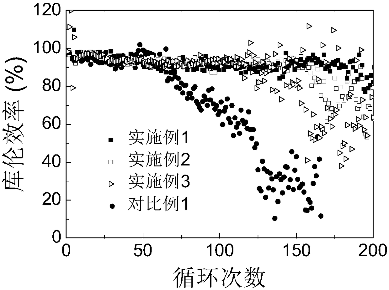
Embodiment 1
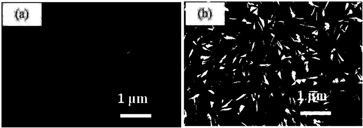
[0037] This embodiment provides a stable lithium metal negative electrode, including a negative electrode current collector and a negative electrode active material layer attached to the surface of the current collector. The negative electrode active material layer is a lithium metal layer. Lithophilic nano-array on the current collector body, and the current collector body is copper foil, the lithium-friendly nano-array is a copper oxide nanosheet array, the thickness of the lithium-friendly nano-array is 0.8 μm-20 μm, and the nano-sheet spacing in the lithium-friendly nanoarray is 100nm-1μm.
[0038] Its preparation method comprises the following steps:
[0039] Step 1, soak the copper foil with 2mol / L dilute hydrochloric acid for 10 minutes at room temperature, then wash it with deoxygenated ethanol three times, and finally wash it once with deoxygenated deionized water;
[0040] Step 2, soak the copper foil cleaned in step 1 in dilute ammonia solution with a concentration...
Embodiment 2
[0046] The difference from Example 1 is: the reaction time in step 2 is 4 hours, and all the other are the same as Example 1, and will not be repeated here.
Embodiment 3
[0048] The difference from Example 1 is: the reaction time in step 2 is 12 hours, and all the other are the same as Example 1, and will not be repeated here.
PUM
| Property | Measurement | Unit |
|---|---|---|
| Thickness | aaaaa | aaaaa |
| Thickness | aaaaa | aaaaa |
| Thickness | aaaaa | aaaaa |
Abstract
Description
Claims
Application Information