
Reforming reactor used in vapor reforming hydrogen production device

A technology of steam reforming and reforming reactor, which is applied in the directions of hydrogen, steam generation, climate sustainability, etc., can solve the problem that the waste heat of high temperature flue gas is not fully utilized, the structure of the reforming reactor is complicated, and the cost of hydrogen production is high. and other problems, to achieve the effect of reducing equipment space, improving speed and conversion rate, and simplifying structure

Pending Publication Date: 2018-08-31
ZHANGJIAGANG RES INST OF HYDROGEN ENERGY CO LTD
View PDF0 Cites 4 Cited by
  • Summary
  • Abstract
  • Description
  • Claims
  • Application Information

AI Technical Summary

Problems solved by technology

[0003] The above-mentioned reforming reactor has the following defects: 1. It needs to use additional fuel gas for heating, which leads to high cost of hydrogen production
2. Fuel gas and combustion-supporting gas need to be ignited in the shell, and an additional ignition device needs to be installed in the reforming reactor, which makes the structure of the reforming reactor complex
[0004] In addition, currently there are high-temperature flue gases produced by many industries, such as coke oven high-temperature flue gas, most of the waste heat of high-temperature flue gas is not fully utilized, which leads to a large loss of heat energy

Method used


Image

  • Reforming reactor used in vapor reforming hydrogen production device

Examples


Embodiment Construction

[0018] The present invention will be further described in detail below in conjunction with the accompanying drawings and preferred embodiments.

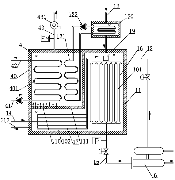
[0019] Such as figure 1 As shown, the reforming reactor in the steam reforming hydrogen production device includes: a shell 11, and the shell 11 is provided with a flue gas input pipe 12, a water vapor input pipe 13, a material delivery pipe 14, and a reformed gas output pipe. Tube 15. The housing 11 is divided into a reforming zone 101 and a heat storage zone 102 . Several reaction tubes 16 are arranged in the reforming zone 101, the flue gas input pipe 12 communicates with the shell 11 at the feed end of the reaction tube 16, and the reformed gas output tube 15 communicates with the discharge end of the reaction tube 16 and extends out of the shell. Body 11. The heat storage area 102 is located on the side of the discharge end of the reaction tube 16. A number of material preheating pipes 17 are arranged in the heat storage area...


PUM


Abstract

The invention discloses a reforming reactor used in a vapor reforming hydrogen production device. The reforming reactor comprises a shell, wherein a flue gas input tube, a vapor input tube, a materialconveying tube and a reformed gas output tube are arranged on the shell; the shell is divided into a reforming zone and a heat accumulation zone; a plurality of reaction tubes are arranged inside thereforming zone; the flue gas input tube is communicated with the shell at reaction tube feeding ends; the reformed gas output tube is communicated with discharge ends of the reaction tubes and extends outside the shell; the heat accumulation zone is positioned on one side of reaction tube outlet ends; a plurality of material preheating tubes are arranged inside the heat accumulation zone; the material conveying tubes are communicated with the input ends of the material preheating tubes; the output ends of the material preheating tubes and the vapor input tube are both communicated with feeding ends of the reaction tubes; a flue gas output mechanism is arranged in the heat accumulation zone. The reforming reactor has the advantages that waste heat of a flue gas can be sufficiently utilized, the hydrogen production cost can be reduced, and the reaction speed and the conversion rate can be effectively increased.

Description

technical field [0001] The invention relates to the technical field of steam reforming hydrogen production equipment, in particular to a reforming reactor. Background technique [0002] At present, the structure of the steam reforming hydrogen production unit mainly includes: reforming reactor, carbon monoxide converter, pressure swing adsorber. Among them, the housing of the reforming reactor is provided with several reaction tubes, and the housing is provided with fuel gas delivery pipes, air delivery pipes, water vapor input pipes, material delivery pipes, reformed gas output pipes, fuel gas delivery pipes and air delivery pipes. The conveying pipes are respectively connected with the shell, so that the gas used as fuel and the gas used for combustion are transported to the shell of the reforming reactor, and one end of the shell with an ignition device is installed for combustion and heating, and the water vapor input pipe and the material conveying pipe They are respec...

Claims


Application Information

Patent Timeline
IPC IPC(8): C01B3/36C01B3/48F22B1/18
CPCF22B1/1807C01B3/36C01B3/48C01B2203/0833C01B2203/0216B01J2219/00018Y02P20/129Y02E20/30
Inventor 蔡信倪中华吕青青严岩王秋霞魏蔚熊波
Owner ZHANGJIAGANG RES INST OF HYDROGEN ENERGY CO LTD
Learn More