
Coal gasification-gas base shaft furnace direct reduction system and technology

A gas-based shaft furnace and coal-to-gas technology, applied in shaft furnaces, combustible gas manufacturing, furnaces, etc., to achieve the effects of long life of furnace tubes, simple equipment, and high thermal efficiency

Active Publication Date: 2018-09-07
NORTHEASTERN UNIV +1
View PDF4 Cites 2 Cited by
  • Summary
  • Abstract
  • Description
  • Claims
  • Application Information

AI Technical Summary

Problems solved by technology

However, there are still many problems in the connection between the coal-based reducing gas system and the gas-based shaft furnace direct reduction system, which still need to be solved by the majority of metallurgists

Method used


Image

  • Coal gasification-gas base shaft furnace direct reduction system and technology
  • Coal gasification-gas base shaft furnace direct reduction system and technology
  • Coal gasification-gas base shaft furnace direct reduction system and technology

Examples


Embodiment 1

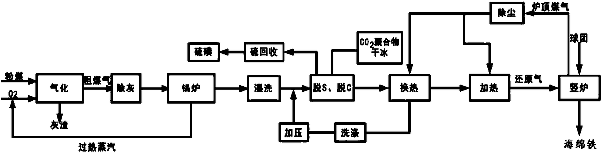
[0042] refer to figure 1 , this embodiment provides a coal-based gas-based shaft furnace direct reduction system, including a coal-based reducing gas system and a gas-based shaft furnace direct reduction system, wherein the coal-based reducing gas system includes a gas production unit, ash removal and wet cleaning unit , purification unit and heat exchange unit, the gas-based shaft furnace direct reduction system includes a reducing gas heating unit and a gas-based shaft furnace unit.

[0043] Specifically, the gas production unit is used to make pulverized coal into a gas rich in carbon monoxide (CO) and hydrogen (H 2 ) of crude gas, the ash removal and wet cleaning unit is used for deashing and wet cleaning of the crude gas, and the purification unit is used for desulfurization and decarbonization of the crude gas output from the ash removal and wet cleaning unit to obtain clean gas. The heat exchange unit is used to exchange heat between the clean coal gas and the top gas ...

Embodiment 2

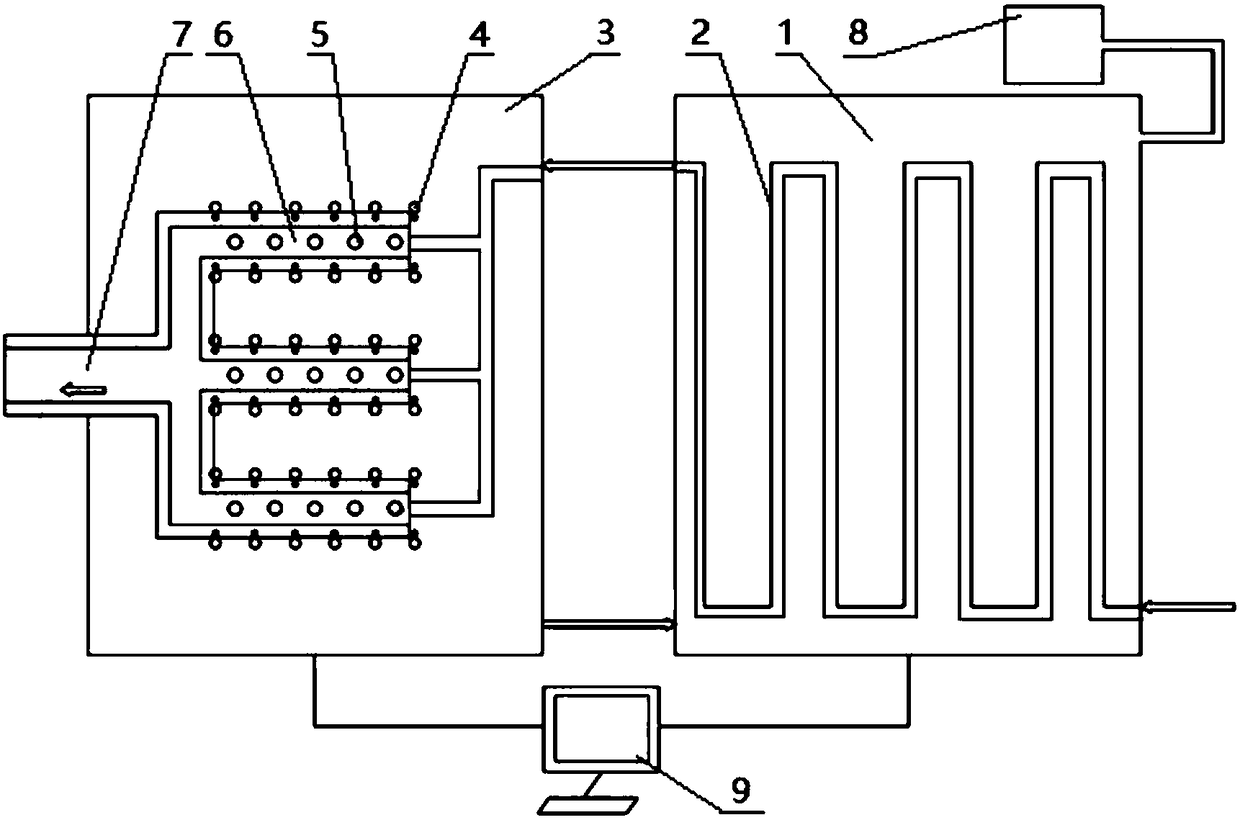
[0082] This embodiment mainly provides the detailed structure of the reducing gas heating unit mentioned in the above embodiment 1, including the preheating furnace 1 and the heating furnace 3, specifically as follows:

[0083] refer to figure 2 A preheating furnace tube 2 is arranged in the preheating furnace 1, and the two ends of the preheating furnace tube 2 pass through the preheating furnace 1 respectively. The part of the preheating furnace tube 2 in the preheating furnace 1 is a zigzag long tube. The space outside the preheating furnace tube 2 in the preheating furnace 1 is the preheating working space.

[0084] The heating furnace 3 is provided with an array of heating furnace tubes 5, figure 2 The middle heating furnace tubes 5 are vertically arranged in three rows and five rows, parallel to each other, and can also be arranged in shapes such as concentric rings. The heating furnace tube 5 is made of a high temperature resistant alloy, so that the heating furnac...


PUM

PropertyMeasurementUnit
particle diameteraaaaaaaaaa

Abstract

The invention relates to a coal gasification-gas base shaft furnace direct reduction system and technology. The system comprises a coal gasification reduction gas system and a gas base shaft furnace direct reduction system, wherein the coal gasification reduction gas system comprises a gasification unit, a dust removal wet-cleaning unit, a purification unit and a heat transfer unit; the gas base shaft furnace direct reduction system comprises a reduction gas heating unit and a gas base shaft furnace unit; the gasification unit is used for making powdered coal into raw coal gas; the purification unit is used for performing desulfurization and decarbonization to obtain clean coal gas; the heat transfer unit is used for performing heat transfer between the clean coal gas and the furnace top coal gas output from the gas base shaft furnace unit; the reduction gas heating unit is used for heating reduction gas to a preset temperature; and the gas base shaft furnace unit is used for reducingiron ore or oxidized pellets to obtain sponge iron. According to the coal gasification-gas base shaft furnace direct reduction system disclosed by the invention, the sponge iron can be generated by utilizing cheap powdered coal in a manner of low-temperature pure oxygen fluidization, and the limit that natural gas is mainly used as the reduction gas by the gas base shaft furnace is overcome, so that the cost is greatly reduced.

Description

technical field [0001] The invention belongs to the technical field of direct reduction, and in particular relates to a coal-to-gas-gas-based shaft furnace direct reduction system and process. Background technique [0002] Direct reduced iron (DRI), also known as sponge iron, is an iron-containing product obtained by direct reduction of iron ore below the melting temperature. With the reduction of my country's steel production capacity, the increasing pressure of energy conservation and emission reduction of steel enterprises, and the structural adjustment of the steel industry, Chinese steel enterprises can only take the short process route of electric furnace steelmaking. Sponge iron is a substitute for scrap steel, an indispensable impurity diluent for electric furnace smelting of pure and high-quality steel, a high-quality coolant for converter steelmaking, and an indispensable raw material for the development of short iron and steel metallurgy processes. With the incre...

Claims


Application Information

Patent Timeline
Patent Type & Authority Applications(China)
IPC IPC(8): C21B13/02C10J3/46C10J3/84
CPCC10J3/46C10J3/84C21B13/0073C21B13/02Y02P10/143
Inventor 储满生王国栋李峰王正平周渝生唐珏柳政根王佳鑫李胜康刘云太
Owner NORTHEASTERN UNIV
Features
  • Generate Ideas
  • Intellectual Property
  • Life Sciences
  • Materials
  • Tech Scout
  • Unparalleled Data Quality
  • Higher Quality Content
  • 60% Fewer Hallucinations
Learn More