Supercharge Your Innovation With Domain-Expert AI Agents!

Biomass power generation equipment applied to city power grid distribution and application method of biomass power generation equipment

A technology for biomass power generation and power grid power distribution, applied in biochemical equipment and methods, bioreactors/fermenters for specific purposes, biomass post-processing, etc., can solve the problem of reduced resource utilization, high manufacturing costs, and power generation efficiency low problems, to achieve the effect of improving utilization, saving a lot of costs, and saving raw materials

Inactive Publication Date: 2018-09-11
STATE GRID ANHUI ELECTRIC POWER +1
View PDF0 Cites 1 Cited by
  • Summary
  • Abstract
  • Description
  • Claims
  • Application Information

AI Technical Summary

Problems solved by technology

[0003] In the prior art, the structure of biomass power generation equipment is complicated, and the manufacturing cost is high. Each type of biomass power generation has corresponding equipment for power generation, and it cannot be well integrated into waste combustion, landfill gas, and biogas power generation. Combined to form a system of equipment, but a single power generation equipment, the power generation efficiency is not only low, but also the resource utilization rate will be greatly reduced

Method used


Image

  • Biomass power generation equipment applied to city power grid distribution and application method of biomass power generation equipment
  • Biomass power generation equipment applied to city power grid distribution and application method of biomass power generation equipment
  • Biomass power generation equipment applied to city power grid distribution and application method of biomass power generation equipment

Examples


Embodiment Construction

[0021] In order to make the object, technical solution and advantages of the present invention clearer, the present invention will be further described in detail below in conjunction with the accompanying drawings and embodiments. It should be understood that the specific embodiments described here are only used to explain the present invention, not to limit the present invention.

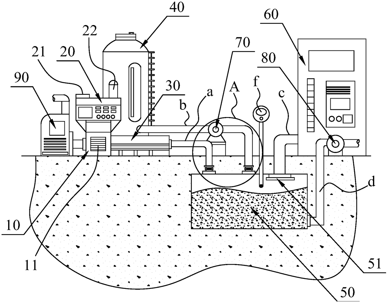
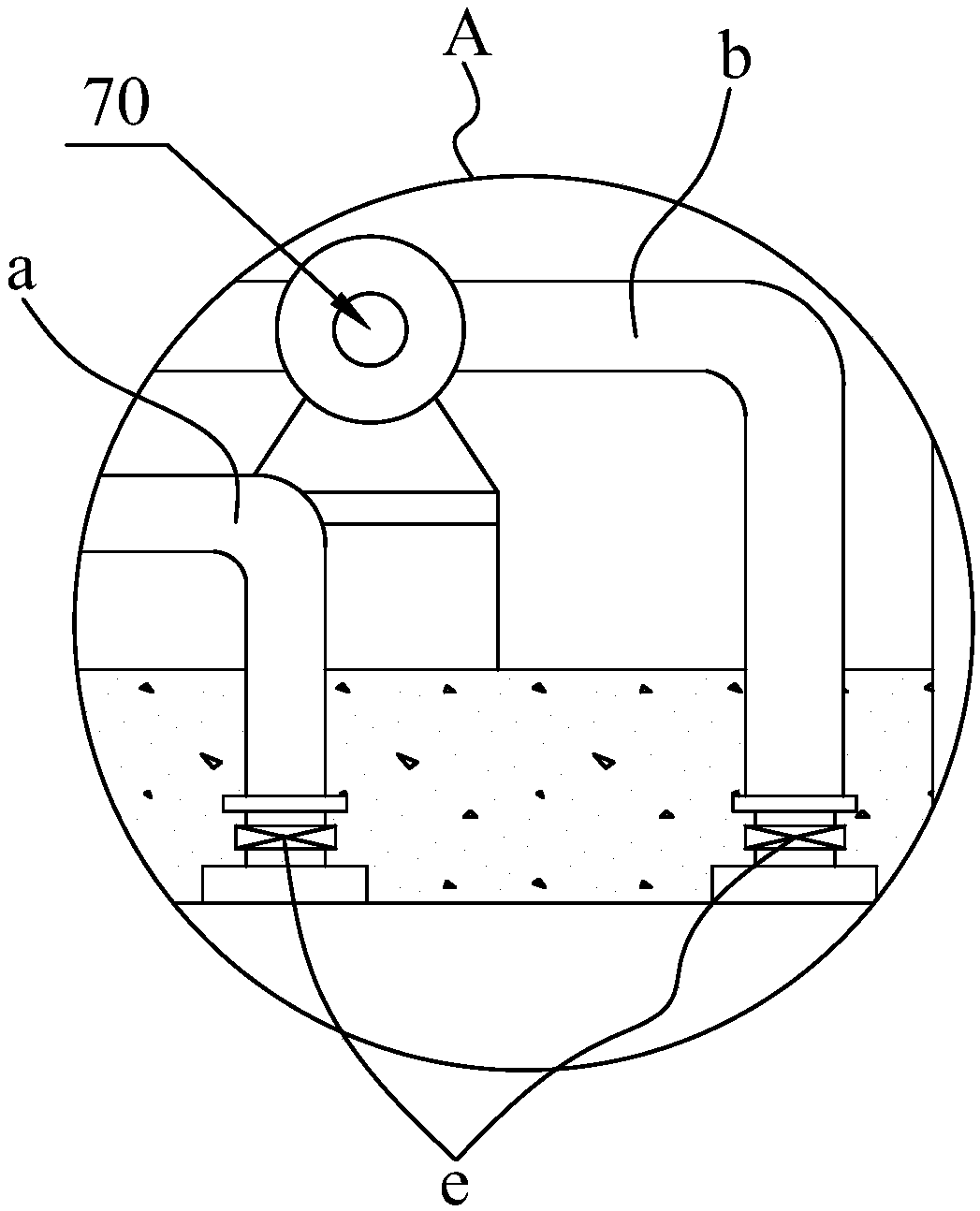
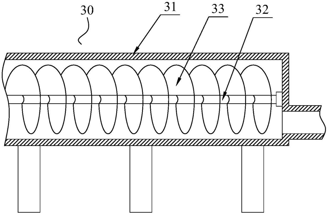
[0022] Please also refer to Figure 1 to Figure 4 ,in figure 1 It is a schematic structural diagram of a biomass power generation equipment applied to power distribution in prefectural and municipal power grids in the present invention; figure 2 for figure 1 Schematic diagram of the enlarged structure of part A in ; image 3 for figure 1 Schematic diagram of the combustion residue discharge device in ; Figure 4 for figure 1 Schematic diagram of the structure of the liquid level alarm device.

[0023] The biomass power generation equipment applied to power distribution in prefectural and mu...


PUM


Abstract

The invention relates to biomass power generation equipment applied to city power grid distribution and an application method of the biomass power generation equipment. The biomass power generation equipment comprises a rubbish combustor, a steam generator, a combustion residue discharging device, a biomass raw material reaction kettle, a biogas fermentation box, biogas power generation equipment,a first delivery pump and a second delivery pump. The steam generator is installed on the rubbish combustor. The rubbish combustor is provided with the combustion residue discharging device. The steam generator is provided with a water inlet and a steam pipe. The biogas fermentation box is arranged underground. A first pipeline is arranged between the combustion residue discharging device and thebiogas fermentation box. A second pipeline is arranged between the biomass raw material reaction kettle and the biogas fermentation box and provided with the first delivery pump. A third pipeline isarranged between the biogas power generation equipment and the biogas fermentation box. The biogas fermentation box is provided with a fourth pipeline. One end of the fourth pipeline is connected withthe bottom end of the biogas fermentation box, the other end of the fourth pipeline extends outside, and the fourth pipeline is provided with the second delivery pump.

Description

technical field [0001] The invention relates to the technical field of power generation equipment for power grids, in particular to biomass power generation equipment applied to power distribution in prefectural and municipal power grids and a method for using the same. Background technique [0002] Biomass power generation is the power generation using the biomass energy of biomass. It is a kind of renewable energy power generation, including direct combustion power generation of agricultural and forestry waste, gasification power generation of agricultural and forestry waste, waste incineration power generation, landfill gas power generation , Biogas power generation. The world's biomass power generation originated in the 1970s. At that time, after the outbreak of the global oil crisis, Denmark began to actively develop clean and renewable energy and vigorously promote biomass power generation such as straw. Since 1990, biomass power generation has been vigorously develop...

Claims


Application Information

Patent Timeline
IPC IPC(8): F01K27/00F01K17/02F01K17/04F01D15/10F02B43/10F02B63/04C12M1/36C12M1/107C12M1/00
CPCC12M21/04C12M41/44C12M43/04C12M43/08C12M45/03F01D15/10F01K17/02F01K17/04F01K27/00F02B43/10F02B63/04F02B2043/103Y02T10/30
Inventor 王文林王正风凌永标王纪旋凌承泽吴旭方林波程金松王松
Owner STATE GRID ANHUI ELECTRIC POWER
Features
  • R&D
  • Intellectual Property
  • Life Sciences
  • Materials
  • Tech Scout
  • Unparalleled Data Quality
  • Higher Quality Content
  • 60% Fewer Hallucinations
Learn More