Laser-assisted horizontal three-dimensional ultrasonic elliptical vibration milling machine equipment and its working method

A laser-assisted, elliptical vibration technology, applied to milling machine equipment, milling machine equipment details, metal processing equipment, etc., can solve the problem of unsolvable micro-motion unit decoupling, difficult to accurately control elliptical vibration trajectory, amplitude and preset value deviation, etc. problem, to achieve the effect of inhibiting the accumulation of nodules and burrs, reducing the electrochemical influence, reducing the cutting force and cutting temperature

Active Publication Date: 2019-12-24
CHANGCHUN UNIV OF SCI & TECH
View PDF3 Cites 0 Cited by
  • Summary
  • Abstract
  • Description
  • Claims
  • Application Information

AI Technical Summary

Problems solved by technology

[0005] The above two technologies are rarely used on milling machines. Ultrasonic elliptical vibration technology cannot solve the problem of decoupling in the orthogonal direction of the micro-motion unit during ultrasonic vibration, and when machining workpieces, affected by machining resistance, ultrasonic vibration When the feed direction is blocked, there is a deviation between the amplitude and the preset value, and it is difficult to accurately control the elliptical vibration trajectory. When the traditional ultrasonic elliptical vibration is used to process hard and brittle materials, the chips are mostly in the shape of particles, which reduces the machining accuracy, and the tool is also very easy to break. The application of laser-assisted processing technology can soften the workpiece to be processed, so that chips are produced in smooth strips, which ensures the quality of the processed surface, increases the service life of the tool, and improves the stability of the machine tool during processing

Method used


Image

  • Laser-assisted horizontal three-dimensional ultrasonic elliptical vibration milling machine equipment and its working method
  • Laser-assisted horizontal three-dimensional ultrasonic elliptical vibration milling machine equipment and its working method
  • Laser-assisted horizontal three-dimensional ultrasonic elliptical vibration milling machine equipment and its working method

Examples


Embodiment Construction

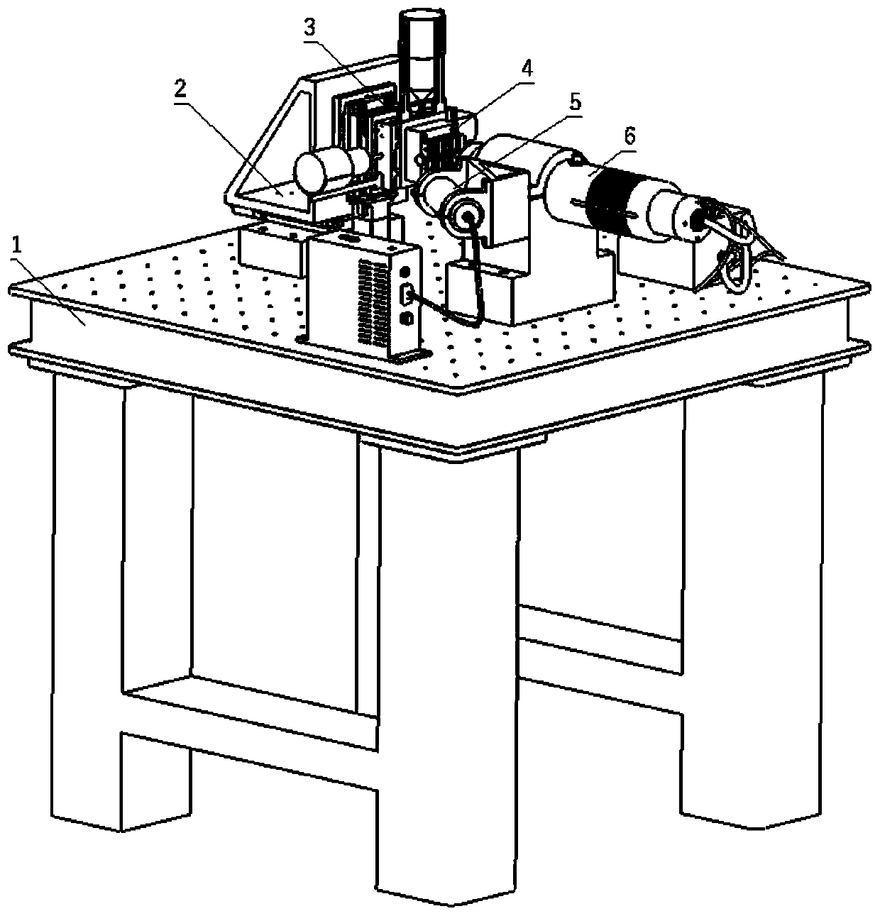
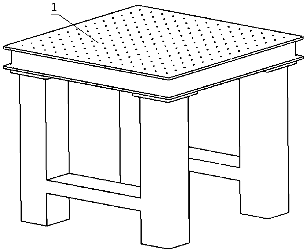
[0040]Laser-assisted horizontal three-dimensional ultrasonic elliptical vibration milling machine equipment and its working method, such as figure 1 with figure 2 As shown, its structure consists of an air-floating platform 1, an XYZ moving assembly 2, a micro-motion unit 3, a workpiece fixture 4, a laser-assisted processing device 5, an ultrasonic electric spindle assembly 6 and other auxiliary components. The air-floating platform 1 is the implementation basis of the present invention, and the XYZ moving assembly 2, the micro-motion unit 3, the workpiece fixture 4, the laser auxiliary processing device 5, the ultrasonic electric spindle assembly 6 and other auxiliary parts are all based on this.

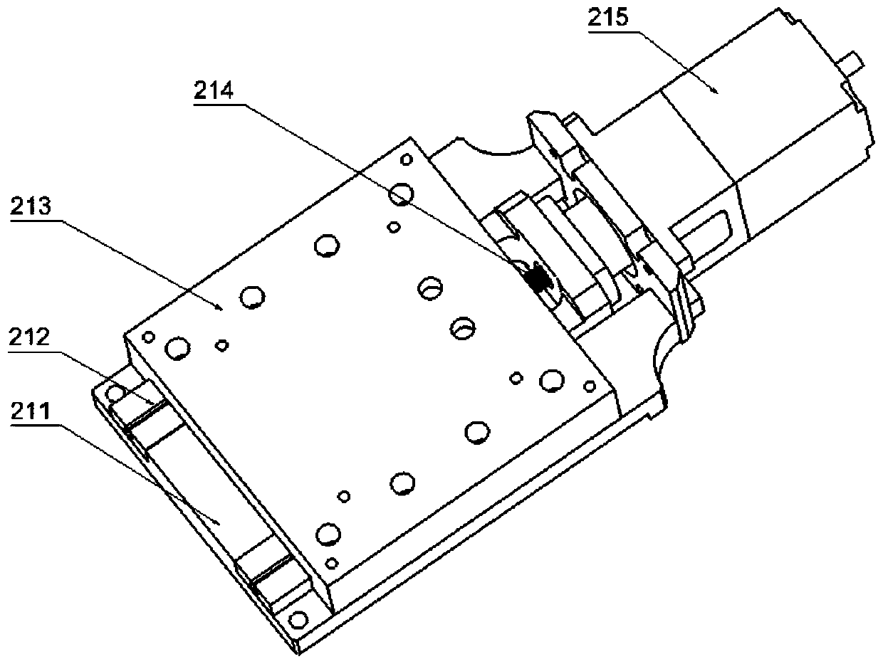
[0041] Such as image 3 As shown, the X-direction mobile unit 202, the Y-direction mobile unit 206 and the Z-direction mobile unit 205 all include a base plate 211, a guide rail 212, a slider 213, a lead screw 214 and a motor 215, and the motor 215 is connected to the lead screw ...


PUM


Abstract

A laser-assisted horizontal three-dimensional ultrasonic elliptical vibration milling machine and its working method belong to the field of ultrasonic vibration cutting technology, including an air-floating platform, an XYZ moving assembly, a micro-motion unit, a workpiece fixture, a laser-assisted processing device, and an ultrasonic electric spindle assembly to make. The laser-assisted horizontal three-dimensional ultrasonic elliptical vibration milling machine involved in the present invention solves the problem that only one-dimensional or two-dimensional ultrasonic vibration can be performed in the mainstream ultrasonic elliptical vibration milling machine in the market. The coupling problem during vibration, through the real-time monitoring and adjustment of the closed-loop control system, accurately controls the vibration trajectory of the ellipse, and through the combination of laser-assisted processing technology, the overall stability of the machine tool is strengthened, and the processing effect is further improved.

Description

technical field [0001] The invention belongs to the technical field of ultrasonic vibration cutting, in particular to a laser-assisted horizontal three-dimensional ultrasonic elliptical vibration milling machine. Background technique [0002] With the continuous development of the processing and manufacturing industry, many new processing methods have been derived, among which ultrasonic elliptical vibration-assisted processing technology and laser-assisted processing technology are particularly popular. These two processing methods have outstanding advantages in processing hard and brittle materials. There are more and more applications in the processing field, especially in aerospace and other fields with significant advantages. [0003] Ultrasonic elliptical vibration technology is used more and more in traditional processing methods such as turning and drilling, and has gradually become the preferred processing method for precision and ultra-precision machining. Ultraso...

Claims


Application Information

Patent Timeline
Patent Type & Authority Patents(China)
IPC IPC(8): B23P25/00B23C3/00B23Q1/25B23Q5/40
CPCB23C3/00B23C2270/10B23P25/006B23Q1/25B23Q5/40
Inventor 于化东梁伟许金凯任万飞于占江廉中旭于朋陈广俊
Owner CHANGCHUN UNIV OF SCI & TECH
Why Eureka
Try Eureka